317
Analog Input Terminals Section 7-4
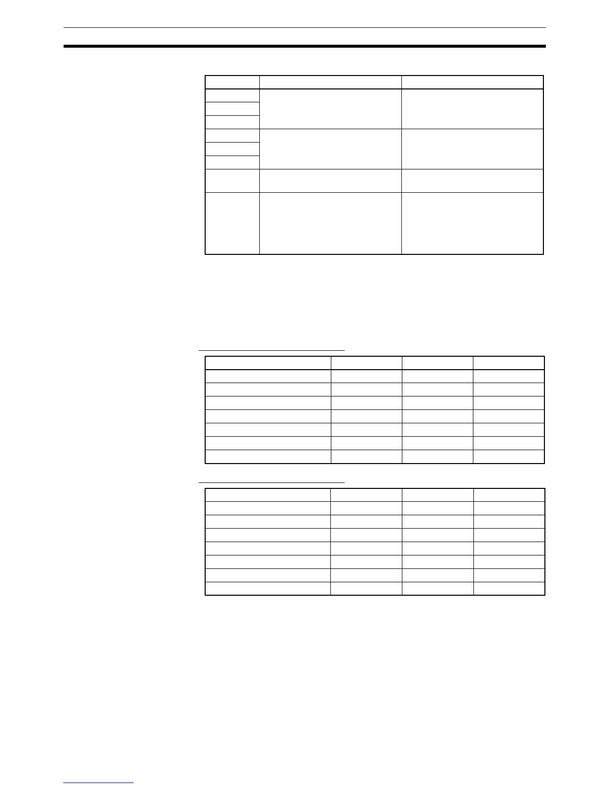
Each pin is set according to the following table.
Note 1. When using the DRT2-AD04H, always set pin 7 to its default setting (OFF).
2. Always set pin 8 to ON if the DIP switch is used to set the ranges. If this pin
is OFF, the DIP switch settings will not be enabled.
3. The DIP switch settings are read when the power is turned ON.
Input Range Settings
■ Inputs 0 and 1 (Shared Setting)
■ Inputs 2 and 3 (Shared Setting)
Note 1. When the DIP switch is used to set the input ranges (pin 8 ON), the input
signal ranges will always be the same for Inputs 0 and 1 and for Inputs 2
and 3. If it is necessary to set separate input signal ranges for Inputs 0 to
3, use the Configurator to make the settings rather than the DIP switch.
When pin 8 is OFF, the other DIP switch settings are disabled.
2. When all the four inputs (inputs 0 to 3) are not being used in the
DRT2-AD04, the number of AD conversion points can be set using the
Configurator to speed up the conversion cycle for each input. Refer to
7-4-3 Functions and Settings and 7-4-4 Calculating the Conversion Cycle
(DRT2-AD04 Only).
Pin No. Setting Specifications
1 Input Terminal: Input range set-
ting for Inputs 0 and 1.
Default setting: All pins OFF
2
3
4 Input Terminal: Input range set-
ting for Inputs 2 and 3.
Default setting: All pins OFF
5
6
7 AD conversion data format setting ON: Signed binary
OFF: Two’s complement
8 Range setting method OFF: Use Configurator.
ON: Use DIP switch.
The other DIP switch settings are
disabled when pin 8 is OFF.
Default setting: OFF
Signal range Pin 1 Pin 2 Pin 3
0 to 5 V OFF OFF OFF
1 to 5 V ON OFF OFF
0 to 10 V OFF ON OFF
–10 to 10 V ON ON OFF
4 to 20 mA OFF OFF ON
0 to 20 mA ON OFF ON
Cannot set for other ranges. --- --- ---
Signal range Pin 4 Pin 5 Pin 6
0 to 5 V OFF OFF OFF
1 to 5 V ON OFF OFF
0 to 10 V OFF ON OFF
–10 to 10 V ON ON OFF
4 to 20 mA OFF OFF ON
0 to 20 mA ON OFF ON
Cannot set for other ranges. --- --- ---

 Loading...


