331
Analog Input Terminals Section 7-4
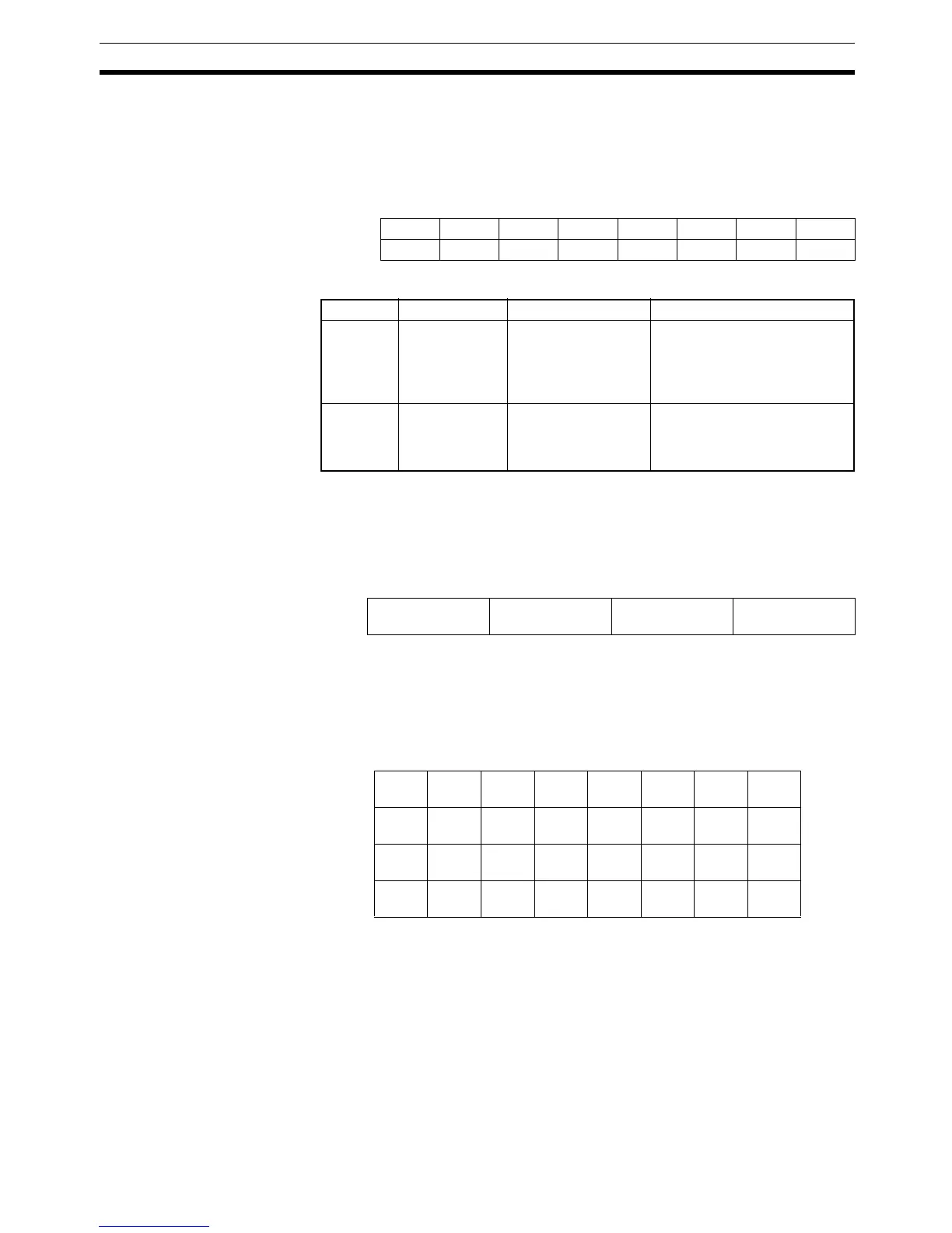
Top/Valley Detection
Timing Flags (Instance
132)
These flags turn ON for the one-shot time when detecting the top or valley for
the top/valley hold function.
These flags are used to time reading the values held as the top and valley val-
ues at the Master. The following data format is used when these flags are allo-
cated in the Master (2 bytes).
The details of each byte are shown in the following table.
Note The one-shot time can be changed. For details, refer to the one-shot time set-
tings for the top/valley hold function.
The following format is used when the Top/Valley Detection Timing Flags are
allocated, starting from the rightmost byte of the Master
Analog Status Flags
(Instance 134)
The Analog Status Flags include allocations for the Comparator Result Flag,
the Top/Valley Detection Timing Flags, and the Off-wire Detection Flags.
These flags are used for detection and monitoring.
The data format used for each byte when these flags are allocated in the Mas-
ter is shown below (4 bytes).
Bit 7 Bit 6 Bit 5 Bit 4 Bit 3 Bit 2 Bit 1 Bit 0
+00000V_ST3V_ST2V_ST1V_ST0
+10000T_ST3T_ST2T_ST1T_ST0
Byte Abbreviation Name Details
+0 V_STx Valley Detection Tim-
ing Flag
Turns ON when a valley is
detected by the valley hold
function and then turns OFF
after the one-shot time has
elapsed.
+1 T_STx Top Detection Timing
Flag
Turns ON when a top is
detected by the top hold func-
tion and then turns OFF after
the one-shot time has elapsed.
Word 15 12 11 8 7 4 3 0
+0 Top Detection
Timing Flag
Valley Detection
Timing Flag
Bit 7 Bit 6 Bit 5 Bit 4 Bit 3 Bit 2 Bit 1 Bit 0
+0 BW0 T_ST0 V_ST0 HH H PS0 L LL Input
0
+1 BW1 T_ST1 V_ST1 HH H PS1 L LL Input
1
+2 BW2 T_ST2 V_ST2 HH H PS2 L LL Input
2
+3 BW3 T_ST3 V_ST3 HH H PS3 L LL Input
3

 Loading...


