333
Analog Input Terminals Section 7-4
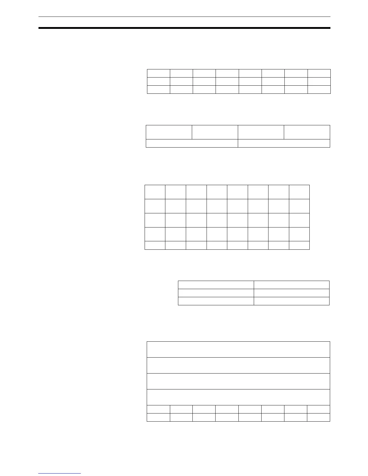
Top/Valley Detection
Timing Flags + Generic
Status Flags (Instance
151)
This data pattern consists of the Top/Valley Detection Timing Flags followed
by Generic Status Flags and is allocated in the Master using the following
data format, shown by byte (3 bytes).
The following format is used when this data pattern is allocated, starting from
the rightmost byte of the Master
.
Analog Status Flags +
Generic Status Flags
(Instance 164)
This data pattern consists of Analog Status Flags followed by Generic Status
Flags and is allocated in the Master using the following data format, shown by
byte (5 bytes).
The following format is used when this data pattern is allocated, starting from
the rightmost byte of the Master
.
Analog Data 1 + Top/Valley
Detection Timing Flags
(Instance174)
This data pattern consists of Analog Data 1 followed by the Top/Valley Detec-
tion Timing Flags and is allocated in the Master using the following data for-
mat (10 bytes).
Bit 7 Bit 6 Bit 5 Bit 4 Bit 3 Bit 2 Bit 1 Bit 0
+00000V_ST3V_ST2V_ST1V_ST0
+10000T_ST3T_ST2T_ST1T_ST0
+2 0 0 MRF CCW RHW NPW 0 0
Word 15 8 7 0
+0 Top Detection
Timing Flags
Valley Detection
Timing Flags
+1 Generic Status Flags
Bit 7 Bit 6 Bit 5 Bit 4 Bit 3 Bit 2 Bit 1 Bit 0
+0 BD0 T_ST0 V_ST0 HH H PS0 LL L Input
0
+1 BD1 T_ST1 V_ST1 HH H PS1 LL L Input
1
+2 BD2 T_ST2 V_ST2 HH H PS2 LL L Input
2
+3 BD3 T_ST3 V_ST3 HH H PS3 LL L Input
3
+4 0 0 MRF CCW RHW NPW 0 0
Word 15 8 7 0
+0 For Input 1 For Input 0
+1 For Input 3 For Input 2
+2 Generic Status Flags
Bit 7 Bit 6 Bit 5 Bit 4 Bit 3 Bit 2 Bit 1 Bit 0
+0
+1
Analog Data 1 for Input 0
+2
+3
Analog Data 1 for Input 1
+4
+5
Analog Data 1 for Input 2
+6
+7
Analog Data 1 for Input 3
+8 0 0 0 0 V_ST3 V_ST2 V_ST1 V_ST0
+9 0 0 0 0 T_ST3 T_ST2 T_ST1 T_ST0

 Loading...


