368
Analog Output Terminals Section 7-5
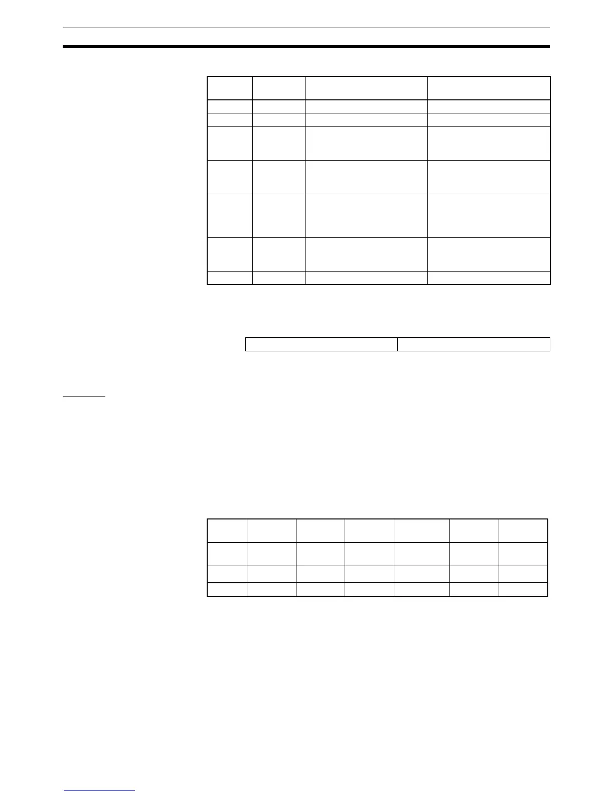
The details of each bit are shown in the following table.
The following format is used when the Generic Status Flags are allocated,
starting from the rightmost byte of the Master
.
7-5-3 Functions and Setting Methods
Scaling The default setting is used to perform AD conversion, converting analog out-
put values that have been scaled to a count of 0 to 6,000 into corresponding
digital values in the output signal range. Scaling can be used to change
scaled values that correspond to the output signal range into other values
required by the user (industry unit values). Scaling also eliminates the need
for ladder programming in the Master to perform math operations. The follow-
ing two methods of scaling can be used.
Default Scaling Default scaling converts analog output values into voltage or current values.
The units used are mV or
µA. When default scaling is selected, scaling is per-
formed according to the output range, as shown in the following table.
Bit Abbrevia-
tion
Name Details
0 --- --- Reserved. (Always 0.)
1 --- --- Reserved. (Always 0.)
2NPWNetwork Power Voltage Mon-
itor Flag
Turns ON when the Network
power level drops below the
set monitor value.
3 RHW Unit Conduction Time Moni-
tor Flag
Turns ON when the Unit ON
time exceeds the set monitor
value.
4 CCW Analog Cumulative Counter
Flag
Turns ON when any of the
cumulated analog values
exceeds the set monitor
value.
5MRFUnit Error Flag Turns ON when analog con-
version stops due to a Unit
error.
6 --- --- Reserved. (Always 0.)
Word 15 8 7 0
+1 Generic Status Flags
Output
range
0 to 5 V 0 to 10 V 1 to 5 V –10 to 10 V 0 to
20 mA
4 to
20 mA
100% 5,000 mV 10,000
mV
5,000 mV 10,000 mV
20,000
µA 20,000 µA
0% 0000 mV 0000 mV 1,000 mV –10,000 mV
0000
µA 4,000 µA
Off-wire --- --- 7FFF hex --- --- 7FFF hex

 Loading...


