447
Remote I/O Communications Characteristics Section 8-1
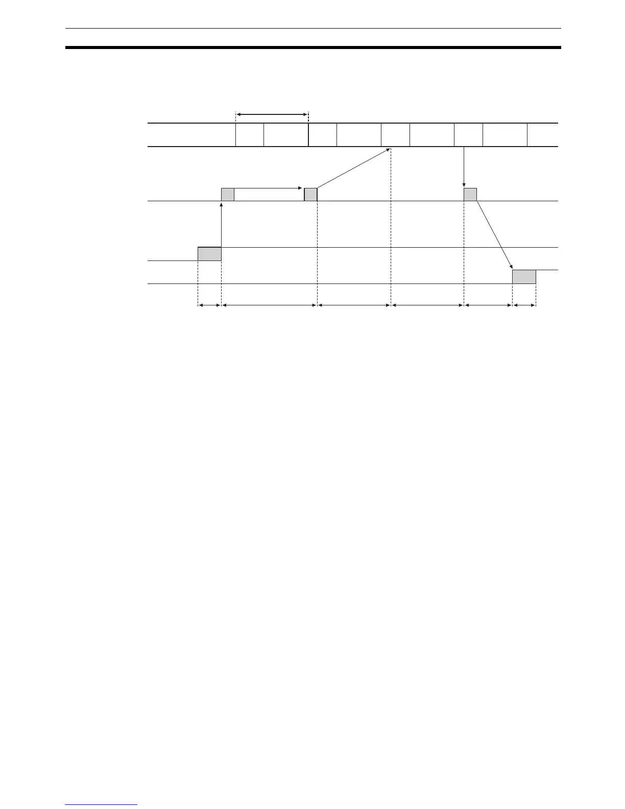
Maximum I/O Response
Time
The maximum I/O response time occurs with the I/O timing shown in the fol-
lowing diagram.
T
IN
: The Input Slave's ON (OFF) delay
T
OUT
: The Output Slave's ON (OFF) delay
T
RM
: The whole Network's communications cycle time (Refer to
page 449.)
T
PLC0
: The PLC's cycle time (instruction execution + peripheral servicing)
Note Refer to SECTION 5 General-purpose Slaves and SECTION 6 Environment-
resistive Slaves for details on Input and Output Slaves' ON and OFF delay
times. Refer to Refresh Time on page 451 and the Operation Manual for the
PLC being used for details on the PLC's instruction execution and peripheral
servicing cycle times.
The maximum I/O response time (T
MAX
) is the total of the following terms:
T
MAX
= T
IN
+ 2 × T
RM
+ 3 × T
PLC0
+ T
OUT
PLC
TPLC0 TOUTTIN TRM+TPLC0 TRMTPLC0
Cycle time
Master Unit
Input
Output
Periph-
eral ser-
vicing
Instruction
execution
Instruction
execution
Periph-
eral ser-
vicing
Periph-
eral ser-
vicing
Instruction
execution
Periph-
eral ser-
vicing
Instruction
execution

 Loading...


