30
Checking Operation Section 2-5
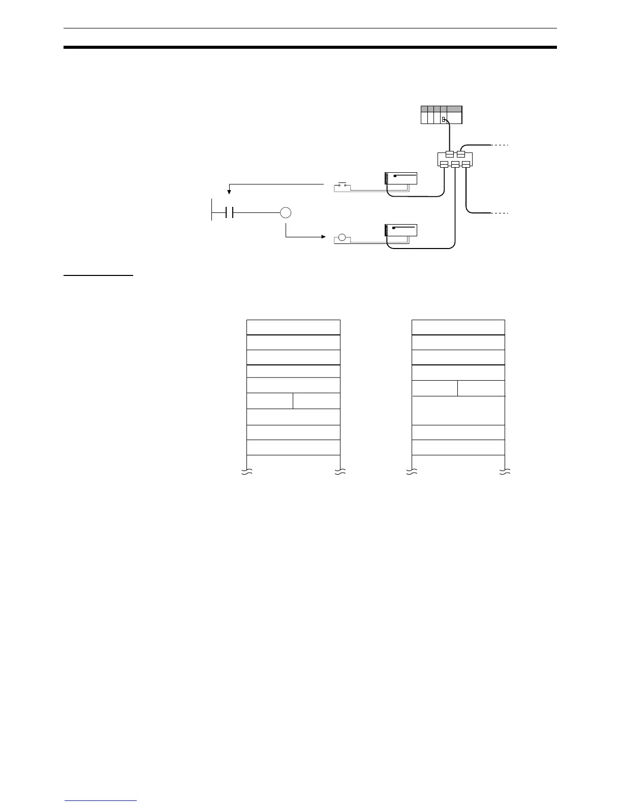
I/O between Remote I/O
Terminals
Create ladder programs in the PLC of the Master Unit, and check that when
the switch on the DRT2-ID16 Input Terminal turns ON, the indicator on the
DRT2-OD16 Output Terminal is ON.
Precautions In the system configuration examples in this section, Slave I/O is allocated in
the Master Unit's CIO Area for fixed remote I/O communications as shown in
the following diagram.
330100 320200
Master Unit
DRT2-ID16 Remote
I/O Terminal
(Node 01)
DRT2-OD16
Remote I/O Terminal
(Node 02)
Switch 1
(bit 00)
Indicator
(bit 00)
CIO 3200
CIO 3201
DRT2-OD16CIO 3202
CIO 3203
CIO 3204
CIO 3205
CIO 3206
CIO 3207
CIO 3208
CIO 3209
CIO 3300
DRT2-ID16CIO 3301
CIO 3302
CIO 3303
CIO 3304
CIO 3305
CIO 3306
CIO 3307
CIO 3308
CIO 3309
DRT2-OD16
XWT-OD08
XWT-ID08
DRT2-ID16
OUT area IN area
Not used
Not used
Not used
Not used
Not used
Not used
Not used
Not used

 Loading...


