40
DeviceNet Remote I/O Communications Section 3-2
Allocating Real I/O Data
and Generic Status Flags
Individually
Instead of allocating real I/O and Generic Status Flags together, they can be
allocated individually. This is only possible, however, if the Master Unit is a
CS/CJ-series DeviceNet Unit and the Configurator is used.
Analog Slaves Data that is allocated for remote I/O communications can be selected using
any of the following methods.
1,2,3... 1. Allocating only analog values (default I/O data)
2. Allocating a fixed I/O data pattern
3. Allocating user-defined I/O data
With methods 2 and 3, the Configurator is used to specify the I/O data that is
to be allocated. An outline of the methods used is given below.
Allocating Fixed I/O Data
Patterns
There are eleven fixed I/O data patterns. The Configurator is used to select
the desired I/O data pattern from the pull-down menu for the Slave's default
connection path in the Edit Device Parameters Window.
Allocating User-defined
I/O Data
Using the Configurator, the desired combination of I/O data can be allocated
for the Master Unit connection. The desired connection is selected from the
Master's Edit Device Parameters Window. Up to two of the eleven I/O data
patterns can be selected for the connection paths of the connection.
Note If analog data is allocated to a COS connection, a frame will be sent to the
host each analog conversion cycle. This will cause frames to be sent fre-
quently, increasing network traffic and possibly affecting the communications
cycle time.
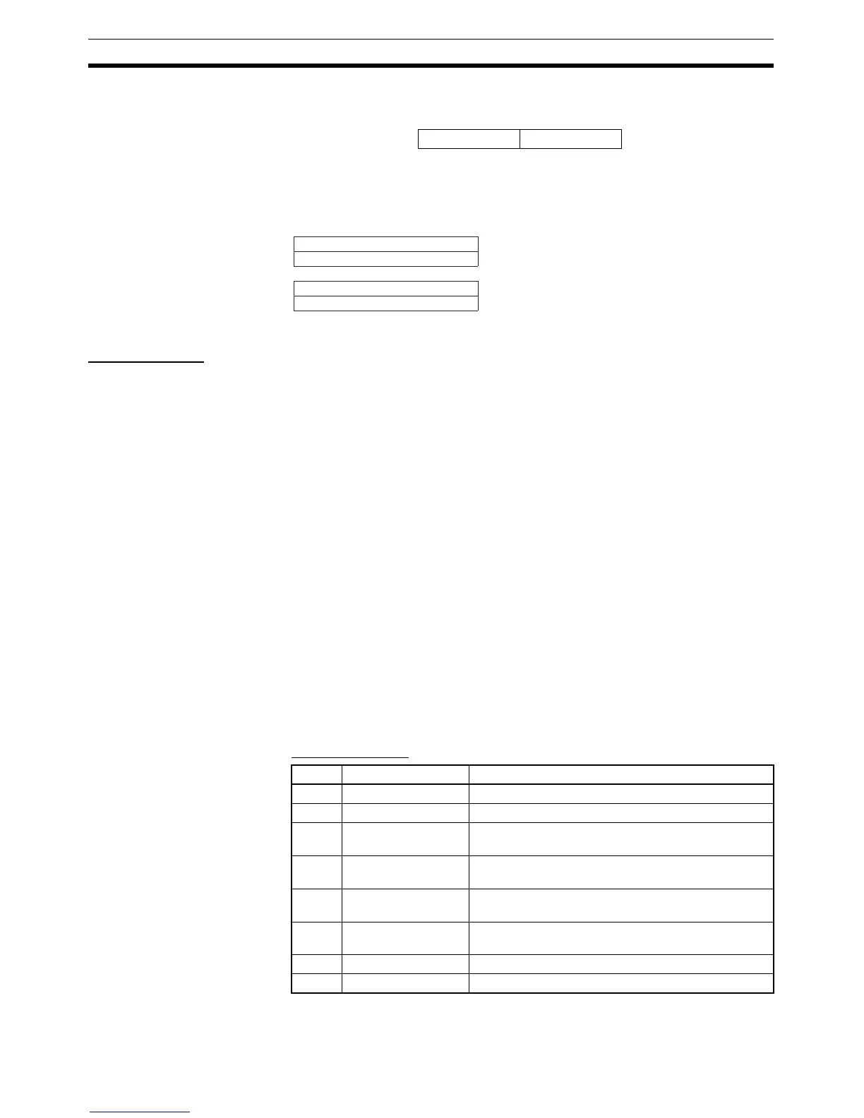
The Generic Status Flags that are allocated are listed in the following tables.
Analog Terminals
IN Area
15 8 7 0
Address header
Generic Status Flags
Allocated 8 inputs.
15 0
:
Node address 00
I/O Area
I/O Area
Node address 01
Node address 00
Node address 01
Status Area
Status Area
Bit Name Description
0 --- Not supported (always 0).
1 --- Not supported (always 0).
2 Network Voltage
Monitor Flag
ON as long as the network power supply remains
below the monitoring set value.
3 Unit Conduction
Time Monitor Flag
Turns ON when the time that power is supplied to the
Unit exceeds the monitoring set value.
4 Cumulative Counter
Flag
Turns ON when any of the cumulative values
exceeds the monitoring set value.
5 Unit Error Flag Turns ON when analog conversion stops due to an
error in the Unit.
6 --- Not supported (always 0).
7 --- Not supported (always 0).

 Loading...


