K
KK
K Power
ON
Confirm
all
of
the
following
items
before
turning
ON
the
power
supply.
• Check
that
the
power
supply
is
of
the
correct
voltage.
200-V
class:
3-phase
200
to
240
V,
50
Hz/60
Hz
400-V
class:
3-phase
380
to
480
V,
50
Hz/60
Hz
• Make
sure
that
the
motor
output
terminals
(U,
V,
W)
and
the
motor
are
connected
correctly.
• Make
sure
that
the
Inverter
control
circuit
terminal
and
the
control
device
are
wired
correctly.
• Set
all
Inverter
control
circuit
terminals
to
OFF.
• When
using
a
PG
Speed
Control
Card,
make
sure
that
it
is
wired
correctly.
• Make
sure
that
the
motor
is
not
connected
to
the
mechanical
system
(no-load
status)
K
KK
K Checking
the
Display
Status
If
the
Digital
Operator's
display
at
the
time
the
power
is
connected
is
normal,
it
will
read
as
follows:
When
an
fault
has
occurred,
the
details
of
the
fault
will
be
displayed
instead
of
the
above
display.
In
that
case,
refer
to
Chapter
7
Troubleshooting.
The
following
display
is
an
example
of
a
display
for
faulty
operation.
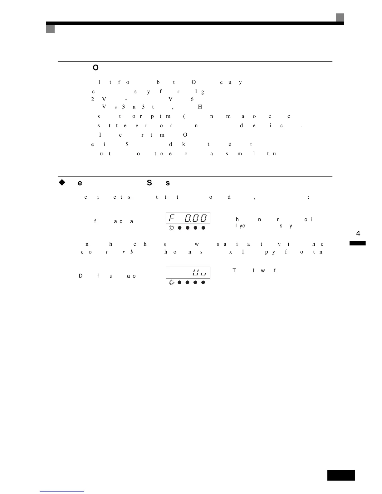
Display for normal operation
The frequency reference monitor is dis-
played in the data display section.
Display for fault operation
The display will differ depending on the
type of fault.
A low voltage alarm is shown at left.
DRIVE QUICK
VERIFY
AUTO
TUNING
ADV
DRIVE QUICK
VERIFY
ADV
AUTO
TUNING

 Loading...


