Digital
Operator
Display
Functions
and
Levels
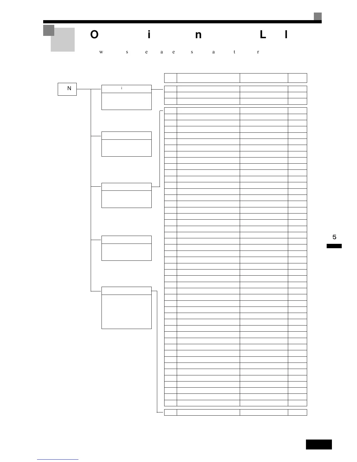
The
following
figure
shows
the
Digital
Operator
display
hierarchy
for
the
Inverter.
MENU
Drive Mode
Inverter can be operated and
its status can be displayed.
Quick Programming Mode
Minimum parameters required
for operation can be monitored
or set.
Advanced Programming Mode
All parameters can be moni-
tored or set.
Verify Mode
Parameters changed from the
default settings can be moni-
tored or set.
Autotuning Mode
Automatically sets motor con-
stants if autotuning data (from
motor nameplate) is input for
open-loop vector control or to
measure the line-to-line resis-
tance for V/f control.
No. Function Display Page
U1 Status Monitor Parameters Monitor 5-75
U2 Fault Trace Fault Trace 5-79
U3 Fault History Fault History 5-80
A1 Initialize Mode Initialization 5-9
A2 User-set Parameters User Parameters 5-10
b1 Operation Mode Selections Sequence 5-11
b2 DC Injection Braking DC Braking 5-12
b3 Speed Search Speed Search 5-13
b4 Timer Function Delay Timers 5-14
b5 PID Control PID Control 5-15
b6 Dwell Functions Reference Hold 5-17
b8 Energy Saving Energy Saving 5-18
C1 Acceleration/Deceleration Accel/Decel 5-19
C2 S-curve Acceleration/Deceleration S-Curve Acc/Dcc 5-21
C3 Motor Slip Compensation Motor-Slip Comp 5-22
C4 Torque Compensation Torque Comp 5-23
C5 Speed Control (ASR) ASR Tuning 5-24
C6 Carrier Frequency Carrier Freq 5-25
d1 Preset Reference Preset Reference 5-27
d2 Reference Limits Reference Limits 5-29
d3 Jump Frequencies Jump Frequencies 5-29
d4 Reference Frequency Hold Sequence 5-30
d6 Field Weakening Field-weakening 5-31
E1 V/f Pattern V/f Pattern 5-31
E2 Motor Setup Motor Setup 5-33
E3 Motor 2 V/f Pattern V/f Pattern 2 5-35
E4 Motor 2 Setup Motor Setup 2 5-37
F1 PG Option Setup PG Option Setup 5-38
F4 Analog Monitor Cards A0-08, 12 Setup 5-41
F5 Not Used D0-02, 08 Setup 5-43
F6 Communications Option Card CP-916 Setup 5-44
H1 Multi-function Digital Inputs Digital Inputs 5-45
H2 Multi-function Digital Outputs Digital Outputs 5-47
H3 Analog Inputs Analog Inputs 5-49
H4 Multi-function Analog Outputs Analog Outputs 5-52
H5 RS-422A/485 Communications Serial Com Setup 5-53
H6 Pulse Train Pulse I/O Setup 5-54
L1 Motor Overload Motor Overload 5-56
L2 Power Loss Ridethrough PwrLoss Ridethru 5-57
L3 Stall Prevention Stall Prevention 5-59
L4 Reference Detection Ref Detection 5-61
L5 Fault Restart Fault Restart 5-62
L6 Torque Detection Torque Detection 5-63
L7 Torque Limits Torque Limit 5-65
L8 Hardware Protection Hdwe Protection 5-65
N1 Hunting Prevention Function Hunting Prev 5-67
N2 Speed Feedback Protection Control AFR 5-68
N3 High-slip Braking High Slip 5-69
o1 Monitor Select Monitor Select 5-69
o2 Multi-function Selections Key Selections 5-71
o3 Copy Function COPY Function 5-73
T
Motor Autotuning Auto-Tuning 5-73

 Loading...


