48
n
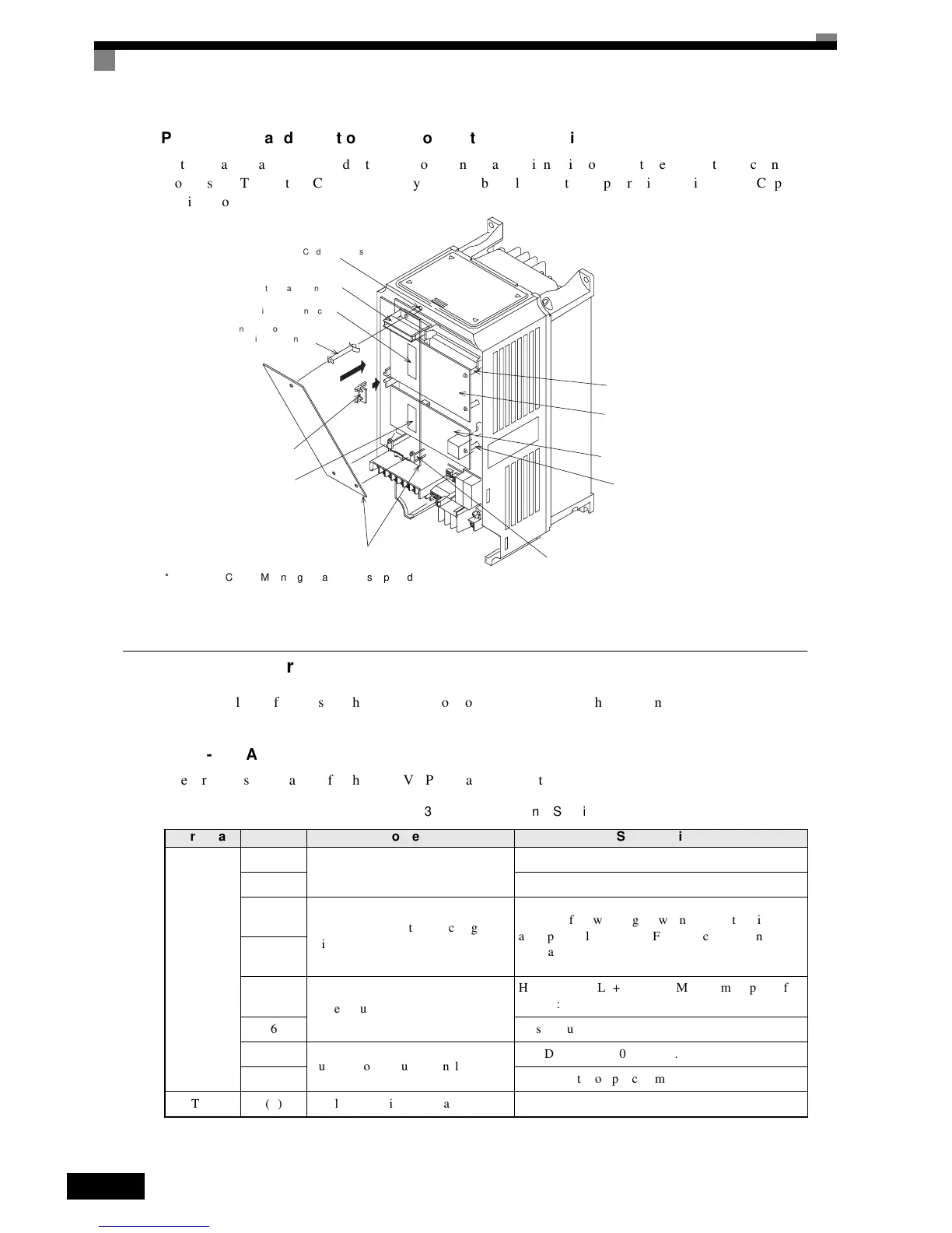
Preventing
C
and
D
Option
Card
Connectors
from
Rising
After
installing
an
Option
Card
into
slot
C
or
D,
insert
an
Option
Clip
to
prevent
the
side
with
the
connector
from
rising.
The
Option
Clip
can
be
easily
removed
by
holding
onto
the
protruding
portion
of
the
Clip
and
pulling
it
out.
* An Option Card in Mounting Location D is supported by Asian Models only. Other models do not have the CN3 connector shown in Fig
2.34.
Fig 2.34 Mounting Option Cards
K
KK
K PG
Speed
Control
Card
Terminals
and
Specifications
The
terminal
specifications
for
the
PG
Speed
Control
Cards
are
given
in
the
following
tables.
n3G3FV-PPGA2
The
terminal
specifications
for
the
3G3FV-PPGA2
are
given
in
the
following
table.
Table 2.25 3G3FV-PPGA2 Terminal Specifications
Terminal No. Contents Specifications
TA 1
1
Power
supply
for
pulse
generator
12
VDC
(±5%),
200
mA
max.
20
VDC
(GND
for
power
supply)
3
+12
V/open
collector
switching
ter-
minal
Terminal
for
switching
between12
V
voltage
input
and
open
collector
input.
For
open
collector
input,
short
across
3
and
4.
4
5
Pulse
input
terminal
H:
+4
to
12
V;
L:
+1
V
max.
(Maximum
response
fre-
quency:
30
kHz)
6Pulse
input
common
7
Pulse
motor
output
terminal
12
VDC
(±10%),
20
mA
max.
8Pulse
monitor
output
common
TA2 (E) Shield
connection
terminal -
A Option Card mounting spacer hole
4CN
A Option Card connector
2CN
C Option Card connector
A Option Card mounting spacer
(Provided with A Option Card.)
Option Clip
(To prevent raising of
C and D Option Cards)
3CN
D Option Card connector*
A Option Card
A Option Card mounting spacer
D Option Card mounting spacer
C Option Card mounting spacer
D Option Card
C Option Card

 Loading...


