EasyManuals Logo

Omron SYSDRIVE 3G3RV Series User Manual

Omron SYSDRIVE 3G3RV Series
446 pages
To Next Page IconTo Next Page
To Previous Page IconTo Previous Page
Page #436 background imageLoading...
Page #436 background image
W
iring Examples
1
0
-
1
3
10
K
KK
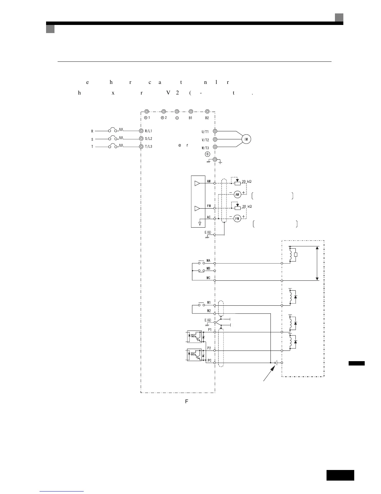
K Using Contact and Open Collector Outputs
This
example
shows
wiring
for
contact
outputs
and
open
collector
outputs.
The
following
example
is
for
the
3G3RV-A2075
(200-V
class
Inverter
for
7.5
kW).
Fig 10.9
Inverter
G
round
E
rror contact output
O
pen collector 1
M
ulti-function
o
pen collector output
4
8 VDC 50 mA max.
(Default: zero speed)
Multi-function output
(
Default: RUN)
3-phase power
MCCB
M
ulti-function analog output 1
-
10 to +10 V 2 mA
D
efault: output frequency,
0
to +10 V
D
efault: Ouput current,
0
to +10 V
-
10 to +10 V 2 mA
Multi-function analog output 2
Frequency meter scale adjustment resistor
Ammeter scale adjustment resistor
M
otor
Sequence external power
supply
S
urge
a
bsorber
2
50 VAC max.
30 VDC max.
Flywheel
diode
4
8 VDC max.
4
8 VDC max.
Sequence
(Default: Freq agree)
250 VAC, 1 A max.
30 VDC, 1 A max.
250 VAC, 1 A max.
30 VDC, 1 A max.
Flywheel
diode
Flywheel
diode
Open collector 2

Table of Contents

Questions and Answers:

Question and Answer IconNeed help?

Do you have a question about the Omron SYSDRIVE 3G3RV Series and is the answer not in the manual?

Omron SYSDRIVE 3G3RV Series Specifications

General IconGeneral
BrandOmron
ModelSYSDRIVE 3G3RV Series
CategoryInverter
LanguageEnglish

Related product manuals