24
nTime
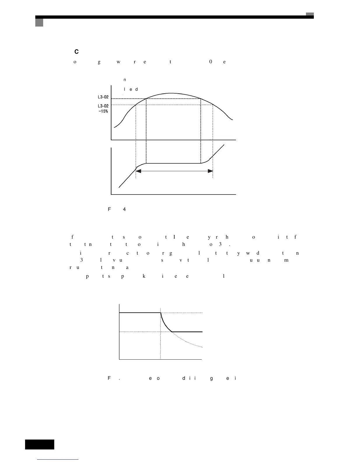
Chart
The
following
figure
shows
the
frequency
characteristics
when
L3-01
is
set
to
1.
Fig 6.24 Time Chart for Stall Prevention During Acceleration
nSetting
Precautions
• If
the
motor
capacity
is
small
compared
to
the
Inverter
capacity,
or
if
the
motor
is
operated
using
the
fac-
tory
settings,
resulting
in
the
motor
stalling,
lower
the
set
value
of
L3-02.
• If
using
the
motor
in
the
constant
output
range,
L3-02
will
be
automatically
lowered
to
prevent
stalling.
L3-03
is
the
limit
value
to
prevent
the
stall
prevention
level
in
the
constant
output
range
from
being
reduced
more
than
necessary.
• Set
the
parameters
as
a
percent
taking
the
inverter
rated
voltage
to
be
100%.
Fig 6.25 Stall Prevention Level and Limit During Acceleration
Output current
Stall level during
acceleration
Time
Time
Output frequency
Output frequency is controlled
to prevent the motor stalling.
Stall prevention level during
acceleration
L3-02 (Stall Prevention Level during Accelera-
tion)
L3-02 x L3-03 (Stall Prevention Limit during Ac-
celeration)
Output frequency
E1-06
Base Frequency (FA)

 Loading...


