78
nCommunications
Specifications
The
RS-422A/485
communications
specifications
are
shown
in
the
following
table.
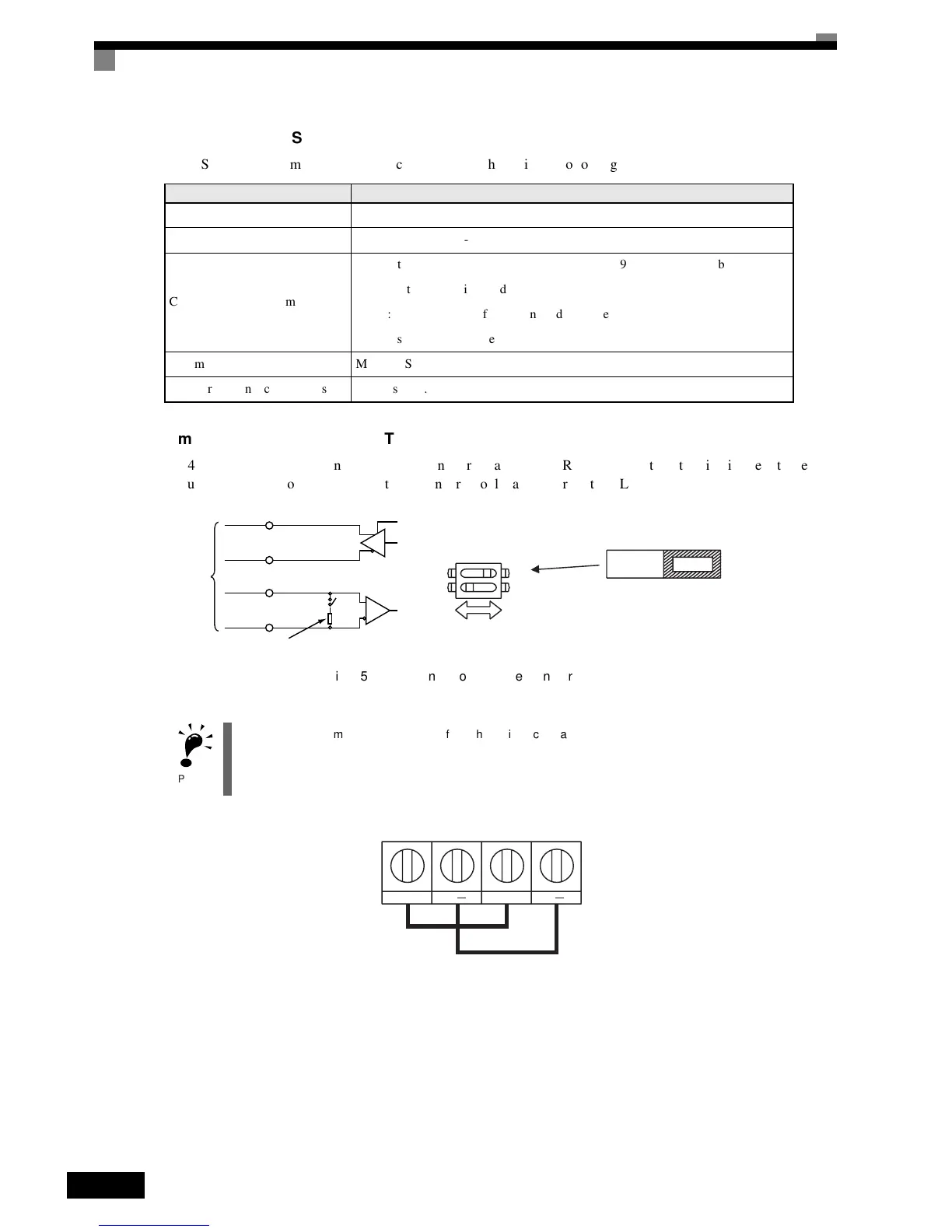
nCommunications
Connection
Terminal
RS-422A/485
communications
use
the
following
terminals:
S+,
S-,
R+,
and
R-.
Set
the
terminating
resistance
by
turning
ON
pin
1
of
switch
S1
for
the
last
Inverter
only,
as
seen
from
the
PLC.
Fig 6.55 Communications Connection Terminal
Item Specifications
Interface RS-422,
RS-485
Communications
Cycle Asynchronous
(Start-stop
synchronization)
Communications
Parameters
Baud
rate: Select
from
1,200,
2,400,
4,800,
9,600,
and
19,200
bps.
Data
length: 8
bits
fixed
Parity: Select
from
even,
odd,
or
none.
Stop
bits: 1
bit
fixed
Communications
Protocol MODBUS
Number
of
Connectable
Units 32
units
max.
(when
using
RS-485)
IMPORTANT
1. Separate the communications cables from the main circuit cables and other wiring and power cables.
2. Use shielded cables for the communications cables, connect the shield cover to the Inverter earth terminal,
and arrange the terminals so that the other end is not connected to prevent operating errors due to noise.
3. When using RS-485 communications, connect S+ to R+, and S- to R-, on the Inverter exterior.
RS-422A
or RS-485
R+
R-
Switch
1
Terminating resistance (1/2 W, 110 Ohms)
S+
S-
+
-
S1
O
F
F
1
2
Terminating
resistance
OFF ON
R+ R S+ S

 Loading...


