1
Slave
Address
Set
the
Inverter
address
from
0
to
32.
If
you
set
0,
commands
from
the
master
will
be
broadcast
(i.e.,
the
Inverter
will
not
return
responses).
Function
Code
The
function
code
specifies
commands.
There
are
three
function
codes,
as
shown
below.
Data
Configure
consecutive
data
by
combining
the
storage
register
address
(test
code
for
a
loopback
address)
and
the
data
the
register
contains.
The
data
length
changes
depending
on
the
command
details.
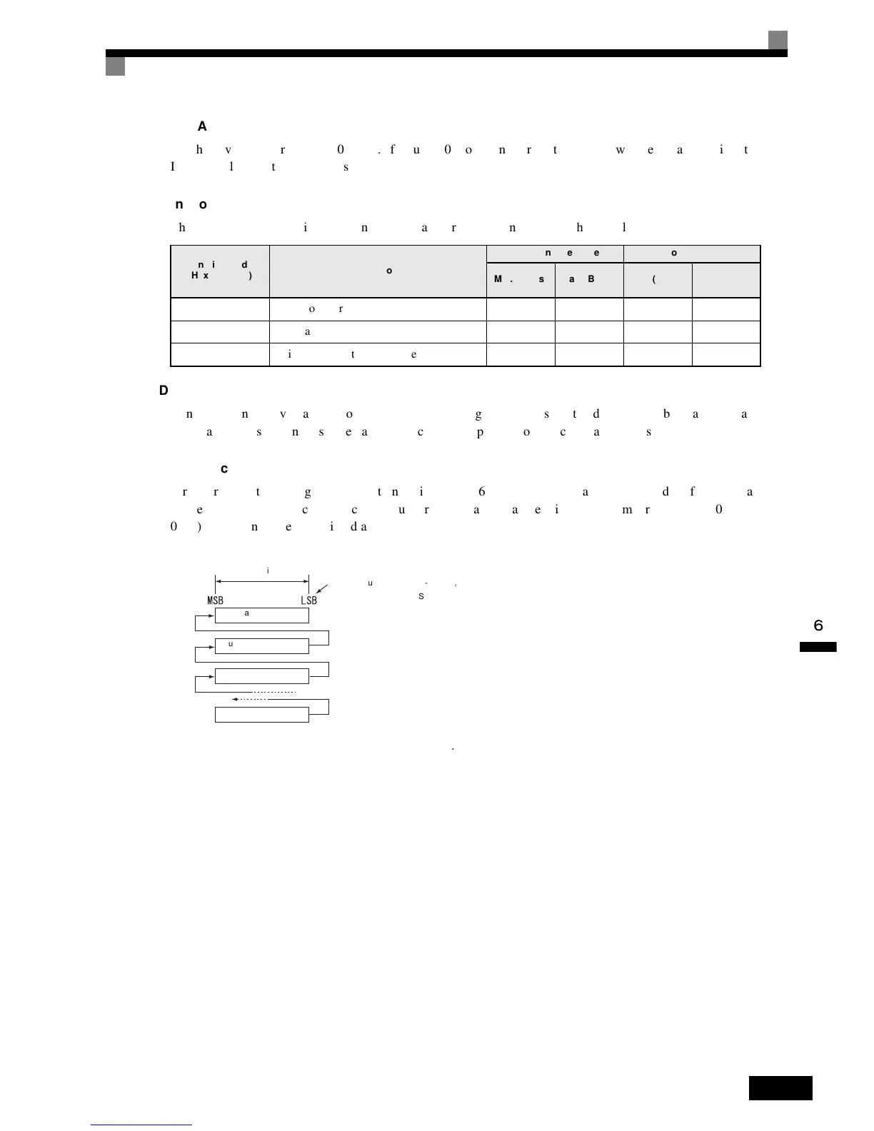
Error
Check
Errors
are
detected
during
communications
using
CRC-16.
The
CRC-16
data
is
the
remainder
of
dividing
all
of
the
message
data
blocks
as
a
continuous
string
of
data
by
a
specific
binary
number
(1
1000
0000
0000
0101),
as
shown
in
the
following
diagram.
Fig 6.59
Function
Code
(Hexadecimal)
Function
Command
Message Response
Message
Min.
(Bytes) Max.
(Bytes) Min.
(Bytes) Max.
(Bytes)
03H Read
storage
register
contents 8 8 7 37
08H Loopback
test 8888
10H Write
multiple
storage
registers 11 41 8 8
8 bits
When calculating the CRC-16 data, the LSB of the slave ad-
dress is treated as the MSB.
Slave address
Function code
Start of communications
data
End of communications
data
Note 1. Although normally the initial value for the CRC-16 calculation is 0, “-1”
(all 16 bits set to 1) is used here instead.
2. The CRC-16 data is calculated using the LSB of the slave address as
the MSB and the last MSB of the communications data as the LSB.
3. Calculate the CRC-16 data for the response message from the slave
and verify that it is the same as the one in the response message.

 Loading...


