88
Note Communications
error
details
are
stored
until
an
error
reset
is
input
(you
can
also
reset
while
the
Unit
is
operating).
Communications
error
details
can
also
be
read
by
using
the
register
numbers
given
in
the
Register
column
in
the
U:
Monitor
parameter
table.
Broadcast
Data
The
following
table
shows
the
broadcast
data.
This
is
write
data
only.
Note Bit
signals
not
defined
in
the
broadcast
operation
signals
use
local
node
data
signals
continuously.
nENTER
Command
When
writing
parameters
to
the
Inverter
from
the
PLC
using
RS-422A/485
communications,
the
parameters
are
temporarily
stored
in
the
parameter
data
area
in
the
Inverter.
To
enable
these
parameters
in
the
parameter
data
area,
use
the
ENTER
command.
There
are
two
types
of
ENTER
commands:
ENTER
commands
that
enable
parameter
data
in
RAM,
and
ENTER
commands
that
write
data
to
EEPROM
(non-volatile
memory)
in
the
Inverter
at
the
same
time
as
enabling
data
in
RAM.
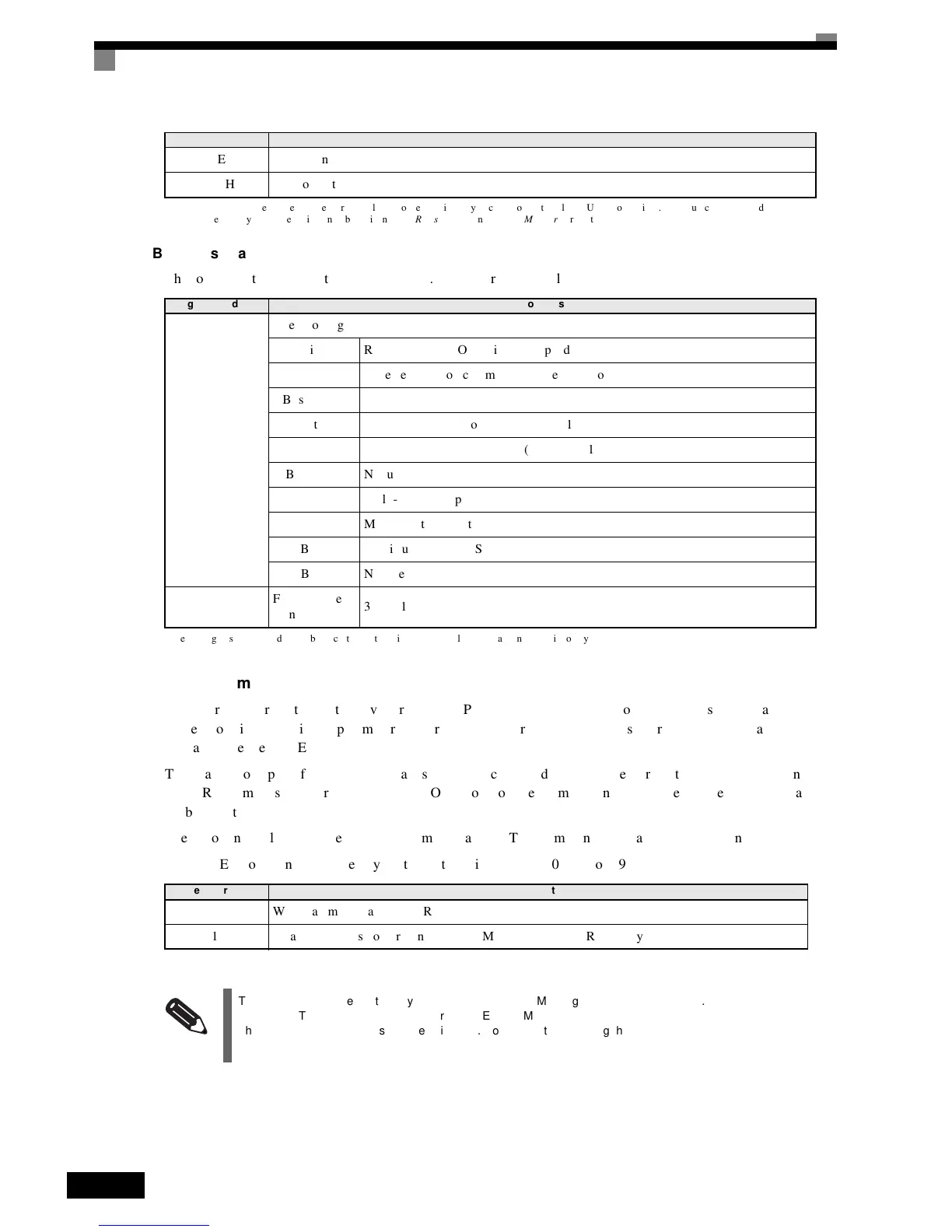
The
following
table
shows
the
ENTER
command
data.
ENTER
command
data
can
only
be
written.
The
ENTER
command
is
enabled
by
writing
0
to
register
number
0900H
or
0901H.
003EH kVA
setting
003FH Control
method
Register
Address Contents
0001H
Operation
signal
Bit
0Run
command
1:
Operating
0:
Stopped
Bit
1Reverse
operation
command
1:
Reverse
0:
Forward
Bits
2
and
3Not
used
Bit
4External
error
1:
Error
(set
using
H1-01)
Bit
5Error
reset
1:
Reset
command
(set
using
H1-02)
Bits
6
to
BNot
used
Bit
C Multi-function
input
S5
Bit
D Multi-function
input
S6
Bit
E Multi-function
input
S7
Bit
FNot
used.
0002H
Frequency
ref-
erence
30000/100%
Register
No. Contents
0900H Write
parameter
data
to
EEPROM
0910H Parameter
data
is
not
written
to
EEPROM,
but
refreshed
in
RAM
only.
INFO
The maximum number of times you can write to EEPROM using the Inverter is 100,000. Do not frequently
execute ENTER commands (0900H) written to EEPROM.
The ENTER command registers are write-only. Consequently, if reading these registers, the register address
will become invalid (Error code: 02H).
Register
No. Contents

 Loading...


