EasyManuals Logo

Omron SYSDRIVE 3G3RV Series User Manual

Omron SYSDRIVE 3G3RV Series
446 pages
To Next Page IconTo Next Page
To Previous Page IconTo Previous Page
Page #393 background imageLoading...
Page #393 background image
M
aintenance and Inspection
8
-
5
n200-V
and
400-V
Class
Inverters
of
22
kW
or
More
A
cooling
fan
is
attached
to
the
top
panel
inside
the
Inverter.
The
cooling
fan
can
be
replaced
without
removing
the
Inverter
from
the
installation
panel.
Removing
the
Cooling
Fan
1. Remove
the
terminal
cover,
Inverter
cover,
Digital
Operator,
and
front
cover
from
the
front
of
the
Inverter.
2. Remove
the
controller
bracket
to
which
the
cards
are
mounted.
Remove
all
cables
connected
to
the
con-
troller.
3. Remove
the
cooling
fan
power
cable
connector
(CN26
and
CN27)
from
the
gate
driver
positioned
at
the
back
of
the
controller.
4. Remove
the
fan
cover
screws
and
pull
out
the
fan
cover
from
the
Inverter.
5. Remove
the
cooling
fan
from
the
fan
cover.
Mounting
the
Cooling
Fan
After
attaching
a
new
cooling
fan,
reverse
the
above
procedure
to
attach
all
of
the
components.
When
attaching
the
cooling
fan
to
the
mounting
bracket,
be
sure
that
the
air
flow
faces
the
top
of
the
Inverter.
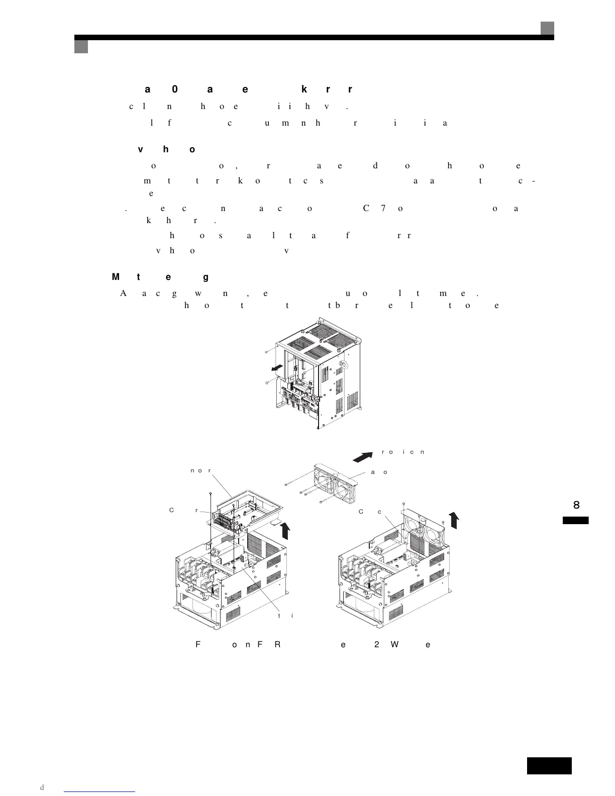
Fig 8.4 Cooling Fan Replacement (Inverters of 22 kW or More)
Controller bracket
Controller
Gate driver
Fan cover
Connector
Air flow direction

Table of Contents

Questions and Answers:

Question and Answer IconNeed help?

Do you have a question about the Omron SYSDRIVE 3G3RV Series and is the answer not in the manual?

Omron SYSDRIVE 3G3RV Series Specifications

General IconGeneral
BrandOmron
ModelSYSDRIVE 3G3RV Series
CategoryInverter
LanguageEnglish

Related product manuals