22
n Input Noise Filters for EMC Directives (3G3RV-PFS@
@@
@, by Schaffner)
When
conformance
to
the
EMC
Directives
in
the
EC
Directives
is
required,
always
use
one
of
these
Filters.
The
Filter
is
connected
between
the
Inverter’s
power
supply
input
terminals
(R/L1,
S/L2,
T/L3)
and
the
power
supply.
There
are
holes
for
mounting
the
Noise
Filters
to
Inverters
on
the
top
of
the
Noise
Filters.
Use
these
holes
to
secure
the
Noise
Filters
to
the
Inverters.
Models and Application
The
standard
models
of
Input
Noise
Filters
for
EMC
Directives
are
listed
in
the
following
table.
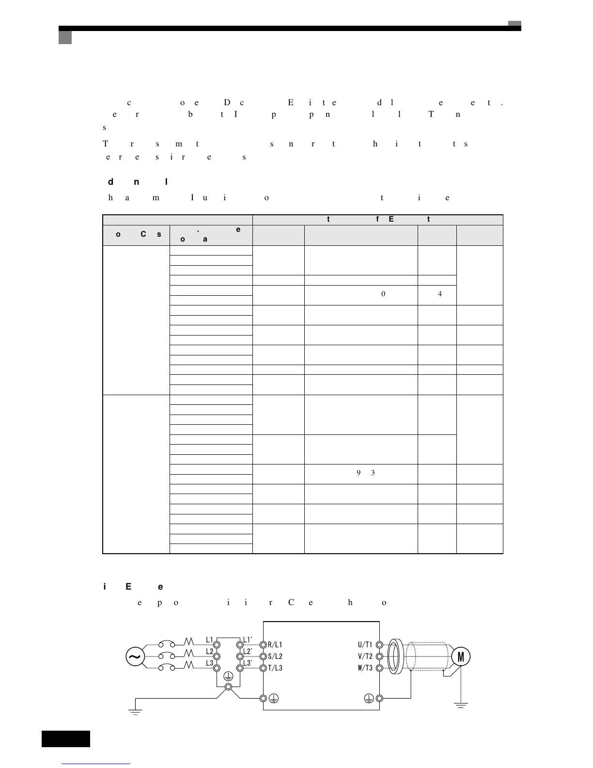
Wiring Example
A
wiring
example
for
an
Input
Noise
Filter
for
EMC
Directives
is
shown
below.
Inverter Input Noise Filter for EMC Directives
Voltage Class
Max. Applicable
Motor Capacity (kW)
Rated Cur-
rent (A)
Model No.
Weight
(kg)
Dimensions
Diagram
3-phase,
200
VA C
0.4
10 3G3RV-PFS5972-10-07 1.1
1
0.75
1.5
2.2 18 3G3RV-PFS5972-18-07 1.3
3.7
35 3G3RV-PFS5973-35-07 1.4
5.5
7.5
60 3G3RV-PFS5973-60-07 3 2
11
15
100 3G3RV-PFS5973-100-07 4.9 3
18.5
22
130 3G3RV-PFS5973-130-35 4.3 5
30
37 160 3G3RV-PFS5973-160-40 6 6
45
240 3G3RV-PFS5973-240-37 11 7
55
3-phase,
400
VA C
0.4
10 3G3RV-PFS5972-10-07 1.1
1
0.75
1.5
2.2
3.7
18 3G3RV-PFS5972-18-07 1.34.0
5.5
7.5
35 3G3RV-PFS5972-35-07 2.1 2
11
15
60 3G3RV-PFS5972-60-07 4 3
18.5
22
70 3G3RV-PFS5972-70-52 3.4 4
30
37
130 3G3RV-PFS5972-130-35 4.7 545
55
3-phase 200 VAC
Single-phase 200 VAC
3-phase 400 VAC
MCCB
Noise filter
Inverter
Clamp core

 Loading...


