40
IMPORTANT
1. Control circuit terminals are arranged as shown below.
2. The output current capacity of the +V and -V terminal is 20 mA.
3. Disable the stall prevention during deceleration (set parameter L3-04 to 0) when using a Braking Resistor
Unit. If this parameter is not changed to disable stall prevention, the system may not stop during decelera-
tion.
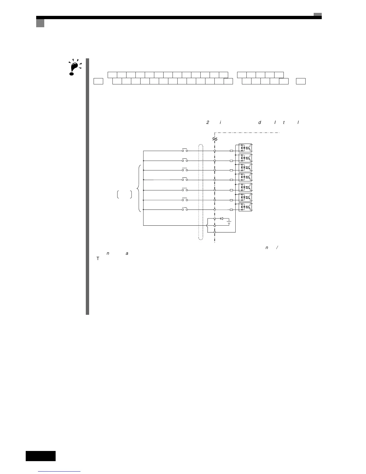
4. Main circuit terminals are indicated with double circles and control circuit terminals are indicated with single
circles.
5. Sequence input signals S1 to S7 are shown in Table
2.23
Sinking/Sourcing
Mode
and
Input
Signals for
sourcing mode connections (+24 V common) for PNP transistor sequence and contacts for European use.
Check your system and select sinking mode or sourcing mode. Refer to Table
2.18
Sinking/Sourcing
Mode
and
Input
Signals.
6. The master speed frequency reference can set to input either a voltage (terminal A1) or current (terminal
A2) by changing the setting of parameter H3-13. The default setting is for a voltage reference input.
See Chapter 6 for the bi-directional voltage input for terminal A1.
7. The multi-function analog output is a dedicated meter output for an analog frequency meter, ammeter, volt-
meter, wattmeter, etc. Do not use this output for feedback control or for any other control purpose.
8. DC reactors to improve the input power factor built into 200-V class Inverters for 22 to 110 kW and 400-V
class Inverters for 22 to 160 kW. A DC reactor is thus an option only for Inverters for 18.5 kW or less.
Remove the short bar when connecting a DC reactor to Inverters for 18.5 kW or less.
9. Set parameter L8-01 to 1 when using a Braking Resistor (3G3IV-PERF). When using a Braking Resistor
Unit, a shutoff sequence for the power supply must be made using a thermal relay trip.
SM SC SP A1 A2 M5 M6 MA M8 MC+V AC -V MP AC RP R+ R-
S1E(G) E(G)S2 S3 S4 S5 M3 M4 M1 M2S6 S7 FM AC AM IG S+ S-

 Loading...


