89
In terms of actual instructions the above diagram would be as follows: The status
of CIO 000000 is loaded (a LOAD instruction) to establish the initial execution
condition. This execution condition is then output using an OUTPUT instruction
to TR0 to store the execution condition at the branching point. The execution
condition is then ANDed with the status of CIO 000001 and instruction 1 is
executed accordingly. The execution condition that was stored at the branching
point is then re-loaded (a LOAD instruction with TR0 as the operand), this is
ANDed with the status of CIO 000002, and instruction 2 is executed accordingly.
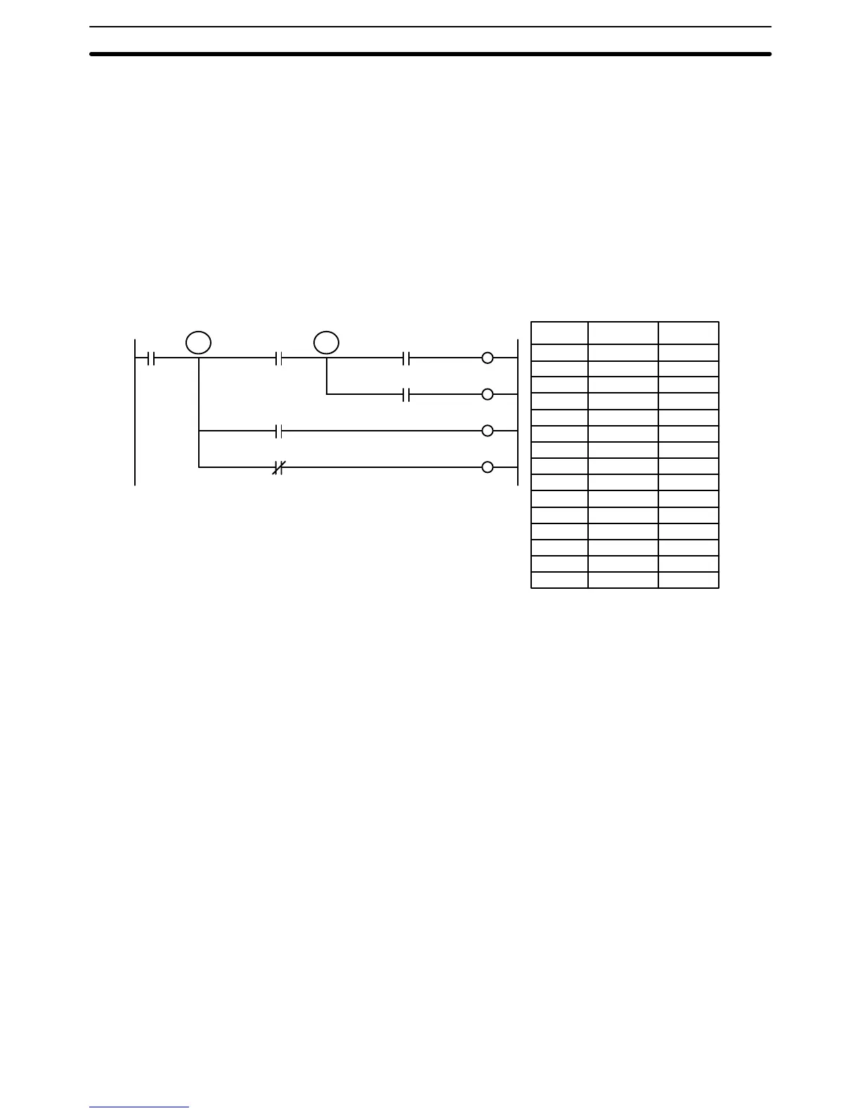
The following example shows an application using two TR bits.
Address Instruction
00000 LD 000000
00001 OUT TR0
00002 AND 000001
00003 OUT TR1
00004 AND 000002
00005 OUT 000500
00006 LD TR1
00007 AND 000003
00008 OUT 000501
00009 LD TR0
00010 AND 000004
00011 OUT 000502
00012 LD TR0
00013 AND NOT 000005
00014 OUT 000503
Operands
0000
05
0000
00
0000
01
0000
02
0000
03
0000
04
0005
00
0005
01
0005
02
0005
03
TR0 TR1
In this example, TR0 and TR1 are used to store the execution conditions at the
branching points. After executing instruction 1, the execution condition stored in
TR1 is loaded for an AND with the status CIO 000003. The execution condition
stored in TR0 is loaded twice, the first time for an AND with the status of
CIO 000004 and the second time for an AND with the inverse of the status of
CIO 000005.
TR bits can be used as many times as required as long as the same TR bit is not
used more than once in the same instruction block. A new instruction block is
begun each time execution returns to the bus bar. If, in a single instruction block,
it is necessary to have more than eight branching points that require the execu-
tion condition be saved, interlocks (which are described next) must be used.
When drawing a ladder diagram, be careful not to use TR bits unless necessary.
Often the number of instructions required for a program can be reduced and
ease of understanding a program increased by redrawing a diagram that would
otherwise required TR bits. In both of the following pairs of diagrams, the bottom
versions require fewer instructions and do not require TR bits. In the first exam-
ple, this is achieved by reorganizing the parts of the instruction block: the bottom
one, by separating the second OUTPUT instruction and using another LOAD
instruction to create the proper execution condition for it.
Branching Instruction Lines Section 4-5