EasyManua.ls Logo

Omron SYSMAC CV Series User Manual

Omron SYSMAC CV Series
636 pages
To Next Page IconTo Next Page
To Previous Page IconTo Previous Page
Page #116 background imageLoading...
Page #116 background image
104
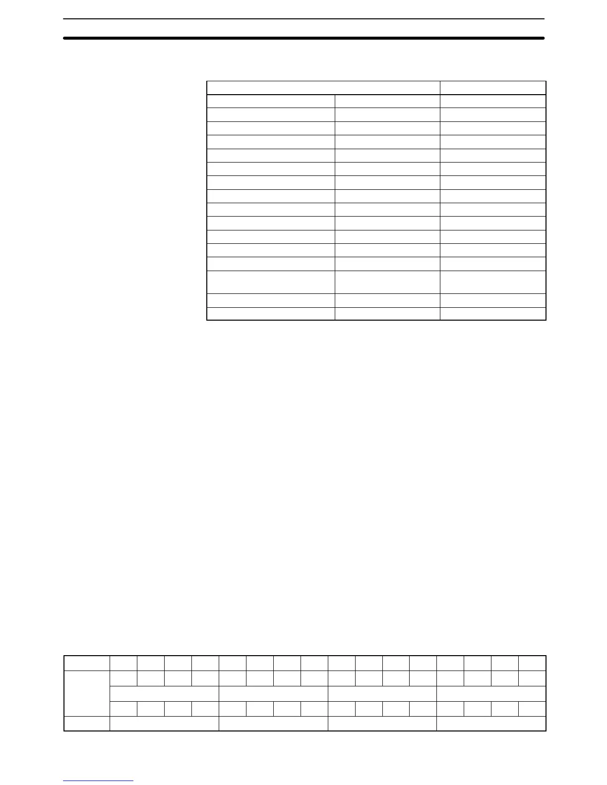
The following table shows the correspondence between the symbol math
instructions and the existing BCD and binary calculation instructions.
Existing instructions Version-2 instructions
BCD ADD ADD(070) +BC (406)
BCD SUBTRACT SUB(071) –BC(416)
BCD MULTIPLY MUL(072)
*B(424)
BCD DIVIDE DIV(073) /B(434)
DOUBLE BCD ADD ADDL(074) +BCL (407)
DOUBLE BCD SUBTRACT SUBL(075) –BCL(417)
DOUBLE BCD MULTIPLY MULL(076)
*BL(425)
DOUBLE BCD DIVIDE DIVL(077) /BL(435)
BINARY ADD ADB(080) +C (402)
BINARY SUBTRACT SBB(081) –C(412)
BINARY MULTIPLY MLB(082)
*U(422)
BINARY DIVIDE DVB(083) /U(432)
DOUBLE BINARY ADD ADBL(084) +CL (403)
DOUBLE BINARY
SUBTRACT
SBBL(085) –CL(413)
DOUBLE BINARY MULTIPLY MLBL(086)
*UL(423)
DOUBLE BINARY DIVIDE DVBL(087) /UL(433)
There are two ways to input symbol math instructions. The first is to input the
symbol directly and the second is to input the function code.
Direct Symbol Input
Direct string inputs are possible using the SYSMAC Support Software. Input the
symbol and the options in order. For example, “+BL(405)” can be entered by
simply inputting “+BL.”
Function Code Input
Function codes can be input using the SYSMAC Support Software or the
CVM1-PRS21-EV1 Programming Console. Simply input the instruction’s func-
tion code.
4-13 Data Formats
The following data formats can be handled by the various calculation and con-
version instructions.
Unsigned binary
Signed binary
Unsigned BCD
Signed BCD
Floating-point
4-13-1 Unsigned Binary Data
Data is configured in words, with 16 bits per word. This data is regarded as 16-bit
binary data. Unsigned binary data is often written as four-digit hexadecimal
(0000 to FFFF).
Bit 15 14 13 12 11 10 09 08 07 06 05 04 03 02 01 00
2
15
2
14
2
13
2
12
2
11
2
10
2
9
2
8
2
7
2
6
2
5
2
4
2
3
2
2
2
1
2
0
2
3
2
2
2
1
2
0
2
3
2
2
2
1
2
0
2
3
2
2
2
1
2
0
2
3
2
2
2
1
2
0
Digit 16
3
16
2
16
1
16
0
Correspondence with
Existing Instructions
Instruction Input Methods
Data Formats Section 4-13

Table of Contents

Question and Answer IconNeed help?

Do you have a question about the Omron SYSMAC CV Series and is the answer not in the manual?

Omron SYSMAC CV Series Specifications

General IconGeneral
SeriesSYSMAC CV Series
TypePLC
Input Voltage100 to 240 VAC, 24 VDC
Number of InputsVaries by model
Number of OutputsVaries by model
I/O CapacityUp to 2048 points
I/O PointsVaries by model
Communication PortsRS-232C, RS-422/485
Programming LanguageLadder Logic
Power Supply100-240V AC or 24V DC
MountingDIN rail mounting
Operating Temperature0°C to 55°C

Summary

PRECAUTIONS

2 General Precautions

User must operate product per specifications; consult OMRON for non-manual conditions or critical systems.

3 Safety Precautions

Precautions regarding power supply, terminal touching, disassembly, repair, and battery handling.

4 Operating Environment Precautions

Guidelines for environmental conditions for PC system installation and operation.

5 Application Precautions

Precautions for safe PC system usage, grounding, power supply, wiring, and program changes.

SECTION 1 Introduction

SECTION 2 Hardware Considerations

2-3 Memory Cards

Covers file memory used to store programs and other data, including RAM, EPROM, and EEPROM types.

2-7 PC Configuration

Provides an overview of the PC configuration, including CPU Rack, Expansion CPU Rack, and Expansion I/O Rack.

SECTION 3 Memory Areas

3-2 Data Area Structure

Describes two sets of addresses for accessing PC memory: data area addresses and memory addresses.

3-3 CIO (Core I/O) Area

Details CIO Area addresses, divided into eight data areas for I/O control and internal data manipulation.

3-6 Auxiliary Area

Contains flags and control bits for monitoring and controlling PC operation, accessing clock pulses, and signaling errors.

SECTION 4 Writing Programs

4-1 Basic Procedure

Outlines basic steps for writing a program, including I/O device list and work bit allocation.

4-3 Basic Ladder Diagrams

Describes ladder diagrams, which consist of vertical lines (bus bars) and branching lines (instruction lines or rungs).

4-7 Controlling Bit Status

Lists instructions used to control individual bit status, such as OUTPUT, SET, RESET, and KEEP.

4-10 Programming Precautions

Provides guidelines on programming practices, such as unlimited conditions in series or parallel and avoiding vertical conditions.

SECTION 5 Instruction Set

5-6 Ladder Diagram Instructions

Covers instructions that correspond to ladder diagram conditions and logic block instructions for complex relationships.

5-7 Bit Control Instructions

Explains instructions used to control bit status by turning bits ON and OFF in different ways.

5-13 Timer and Counter Instructions

Details instructions for creating timers and counters, accessing PVs and Completion Flags.

5-15 Data Movement Instructions

Explains instructions used for moving data between different addresses in data areas.

5-16 Comparison Instructions

Covers instructions used for comparing data, affecting comparison flags and outputting results.

5-17 Conversion Instructions

Explains instructions that convert word data from one format to another, outputting converted data to specified result words.

SECTION 6 Program Execution Timing

6-2 Cycle Time

Explains operations affecting cycle time and I/O response time, and shows basic cycle time calculation.

6-5 I/O Response Time

Explains the time taken for the PC to output a control signal after receiving an input signal.

SECTION 7 PC Setup

SECTION 8 Error Processing

8-4 Error Messages

Classifies errors into initialization, non-fatal operating, and fatal operating errors for message display.

Appendices

A Instruction Set

Details all ladder diagram programming instructions, variations, and applicable data areas.

B Error and Arithmetic Flag Operation

Explains instructions affecting ER, CY, GR, LE, EQ, OF, UF, and N flags.

C PC Setup Default Settings

Lists default values for PC Setup parameters.

D Data Areas

Summarizes data areas in CV-series PCs, including CIO, Temporary Relay, and Auxiliary Areas.

Related product manuals