48
3-3-8 SYSMAC BUS Area
I/O bits allocated in the SYSMAC BUS Area correspond to external I/O points on
I/O Terminals, Optical I/O Units, or I/O Units mounted to Slave Racks that are
connected to SYSMAC BUS Remote I/O Master Units (RM). Up to 8 Masters
can be connected to the CV1000, CV2000, CVM1-CPU11-EV2, or
CVM1-CPU21-EV2, and up to 4 Masters can be connected to the CV500 or
CVM1-CPU01-EV2. The total number of I/O points in the SYSMAC BUS System
must not exceed 2,048 (128 words) for the CVM1-CPU21-EV2, 1024 (64 words)
for the CV1000, CV2000, or CVM1-CPU11-EV2, and 512 (32 words) for the
CV500 or CVM1-CPU01-EV2.
Unit numbers are assigned to Masters automatically when the I/O Table is
registered or edited, according to the order in which the Masters are mounted
(taking into account rack number settings). The first word allocated to each
Master can be changed with the PC Setup using the CVSS/SSS.
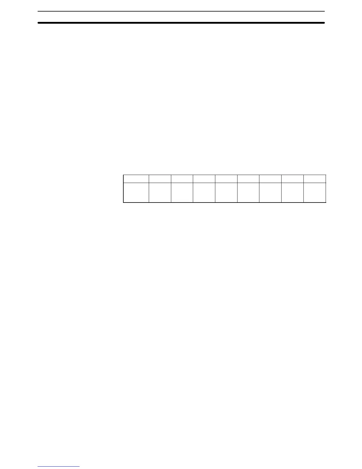
SYSMAC BUS Area addresses range from CIO 2300 through CIO 2555. These
256 words are divided into 8 groups of 32 words each and are allocated to Mas-
ters according their number setting. The following table shows the default ad-
dress allocation.
RM # 0 1 2 3 4 5 6 7
CIO
words
2300
to
2331
2332
to
2363
2364
to
2395
2396
to
2427
2428
to
2459
2460
to
2491
2492
to
2523
2524
to
2555
Words are allocated to Units on Slave Racks in order beginning with the
Slave Rack with the lowest unit number. Up to 8 Slave Racks can be con-
nected to each Master. Word addresses are assigned to Units in the first
Slave Rack in the order in which they are mounted left to right. Word alloca-
tion then continues left to right on the Slave Rack with the next lowest unit
number, and so on until words have been allocated to all of the Slave Racks.
Words are allocated to I/O Terminals and Optical I/O Units according to word set-
tings on the Unit. The word allocated is calculated by adding the first word of the
Master and the word setting on the Unit. To minimize the chance of overlapping
with words allocated to Slave Racks, it is recommended to set I/O Terminal and
Optical I/O Unit settings beginning from 31, the last word allocated to the Master,
and continuing down to lower settings.
Refer to the
SYSMAC BUS Remote I/O System Manual
for details on word
allocation to I/O Terminals and Slave Racks.
After the I/O Table has been registered or edited, an “I” will appear before
input bit addresses and a “Q” will appear before output bit addresses on
CVSS/SSS displays. Refer to the
CVSS/SSS Operation Manuals
for details
on the PC Setup.
3-4 TR (Temporary Relay) Area
The TR Area provides eight bits that are used only with the LD and OUT
instructions to enable certain types of branching ladder diagram program-
ming. It is only necessary to use TR bits when entering the program using
mnemonic code. The CVSS/SSS enters TR bits automatically, although the
TR bits are not shown on the CVSS/SSS screen. The use of TR bits is de-
scribed in
Section 4 Writing Programs
.
TR addresses range from TR0 though TR7. Each of these bits can be used
as many times as required and in any order required as long as the same TR
bit is not used twice in the same instruction block.
TR (Temporary Relay) Area Section 3-4