79
The instruction at the right would have an ON execution condition when any one
of the three conditions was ON, i.e., when CIO 00000 was OFF, when CIO 00100
was OFF, or when CIO 000200 was ON.
OR and OR NOT instructions can be considered individually, each taking the
logical OR between the execution condition produced by the preceding instruc-
tions and the status of the OR instruction’s operand bit. If either one of these
were ON, an ON execution condition would be produced for the next instruction.
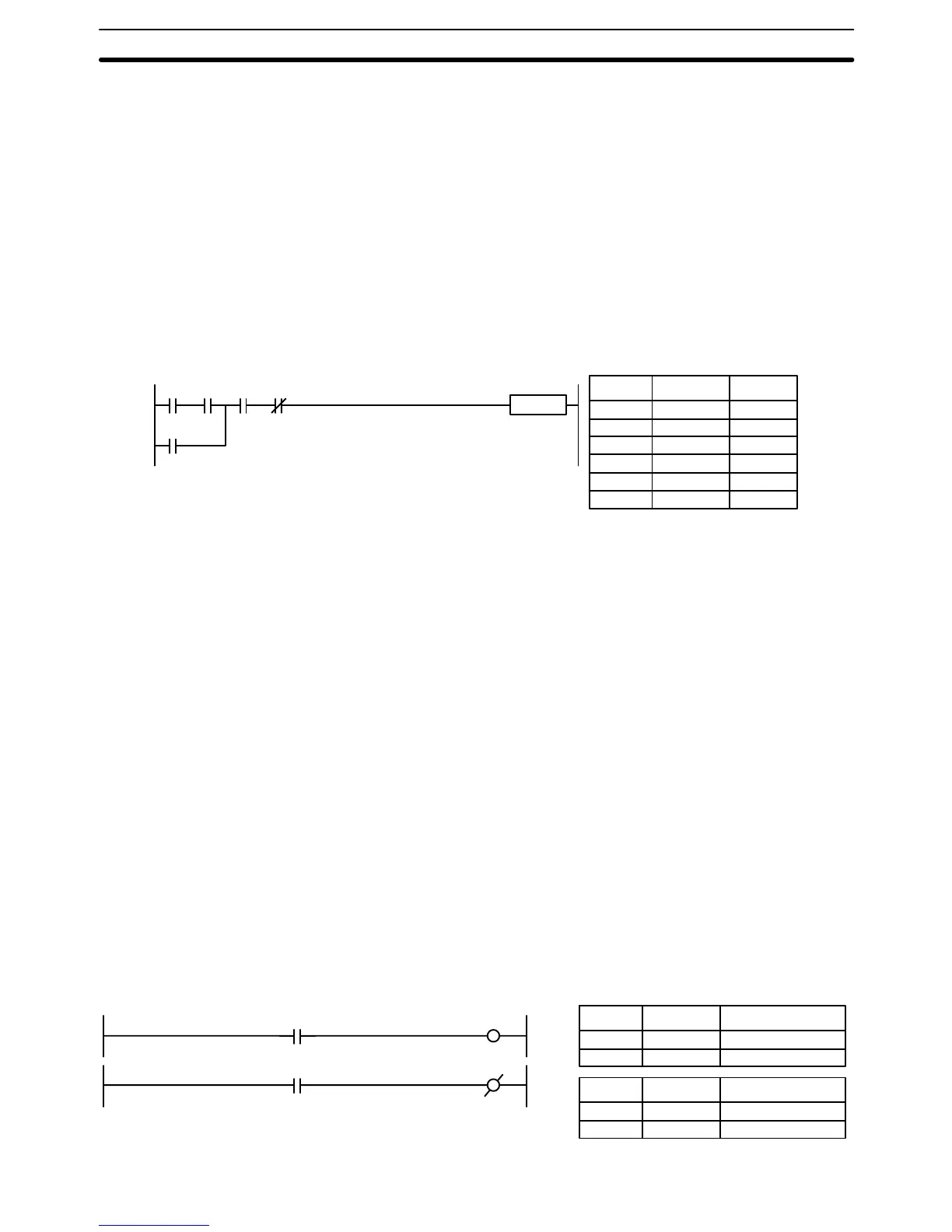
When AND and OR instructions are combined in more complicated diagrams,
they can sometimes be considered individually, with each instruction performing
a logic operation on the current execution condition and the status of the oper-
and bit. The following is one example. Study this example until you are con-
vinced that the mnemonic code follows the same logic flow as the ladder dia-
gram.
Instruction
0000
03
0000
00
0000
01
0000
02
0002
00
Address Instruction Operands
00000 LD 000000
00001 AND 000001
00002 OR 000200
00003 AND 000002
00004 AND NOT 000003
00005 Instruction
Here, an AND is taken between the status of CIO 000000 and that of
CIO 000001 to determine the execution condition for an OR with the status of
CIO 000200. The result of this operation determines the execution condition for
an AND with the status of CIO 000002, which in turn determines the execution
condition for an AND with the inverse (i.e., and AND NOT) of the status of
CIO 000003.
In more complicated diagrams, it is necessary to consider logic blocks before an
execution condition can be determined for the final instruction, and that’s where
AND LOAD and OR LOAD instructions are used. Before we consider more com-
plicated diagrams, however, we’ll look at the instructions required to complete a
simple “input-output” program.
4-3-4 OUTPUT and OUTPUT NOT
The simplest way to output the results of combining execution conditions is to
output it directly with the OUTPUT and OUTPUT NOT. These instructions are
used to control the status of the designated operand bit according to the execu-
tion condition. With the OUTPUT instruction, the operand bit will be turned ON
as long as the execution condition is ON and will be turned OFF as long as the
execution condition is OFF. With the OUTPUT NOT instruction, the operand bit
will be turned ON as long as the execution condition is OFF and turned OFF as
long as the execution condition is ON. These appear as shown below. In mne-
monic code, each of these instructions requires one line.
Address Instruction Operands
00000 LD 000000
00001 OUT 000200
Address Instruction Operands
00000 LD 000001
00001 OUT NOT 000201
0002
00
0002
01
0000
00
0000
01
Combining AND and OR
Instructions
Basic Ladder Diagrams Section 4-3