87
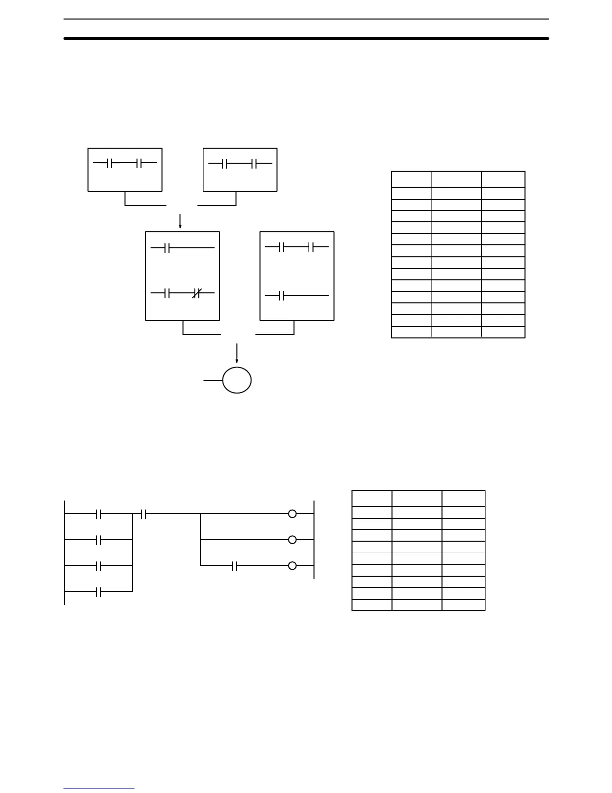
The first logic block instruction is used to combine the execution conditions re-
sulting from blocks a and b, and the second one is to combine the execution
condition of block c with the execution condition resulting from the normally
closed condition assigned CIO 000003. The rest of the diagram can be coded
with OR, AND, and AND NOT instructions. The logical flow for this and the re-
sulting code are shown below.
000000 000001
000500
000002 000003
001000 001001
000004 000005
000500
000006
Block c
Block bBlock a
OR LD
LD 000000
AND 000001
OR 000500
AND 000002
AND NOT 000003
LD 001000
AND 001001
OR 000006
LD 000004
AND 000005
AND LD
00000 LD 000000
00001 AND 000001
00002 LD 001000
00003 AND 001001
00004 OR LD ––
00005 OR 000500
00006 AND 000002
00007 AND NOT 000003
00008 LD 000004
00009 AND 000005
00010 OR 000006
00011 AND LD ––
00012 OUT 000500
Address Instruction Operands
4-4-2 Coding Multiple Right-hand Instructions
If there is more than one right-hand instruction executed with the same execu-
tion condition, they are coded consecutively following the last condition on the
instruction line. In the following example, the last instruction line contains one
more condition that corresponds to an AND with CIO 000400.
Address Instruction
00000 LD 000000
00001 OR 000001
00002 OR 000002
00003 OR 000200
00004 AND 000003
00005 OUT 000001
00006 OUT 000500
00007 AND 000400
00008 OUT 000506
Operands
0000
01
0005
00
0005
06
0000
00
0000
03
0004
00
0000
01
0000
02
0002
00
4-5 Branching Instruction Lines
When an instruction line branches into two or more lines, it is sometimes neces-
sary to use either interlocks or TR bits to maintain the execution condition that
existed at a branching point. This is because instruction lines are executed
across to a right-hand instruction before returning to the branching point to
execute instructions one a branch line. If a condition exists on any of the instruc-
tion lines after the branching point, the execution condition could change during
this time making proper execution impossible. The following diagrams illustrate
Branching Instruction Lines Section 4-5