35
3-1 Introduction
Various types of data are required to achieve effective and correct control. To
facilitate managing this data, the PC is provided with various memory areas
for data, each of which performs a different function. The areas generally ac-
cessible by the user for use in programming are classified as data areas.
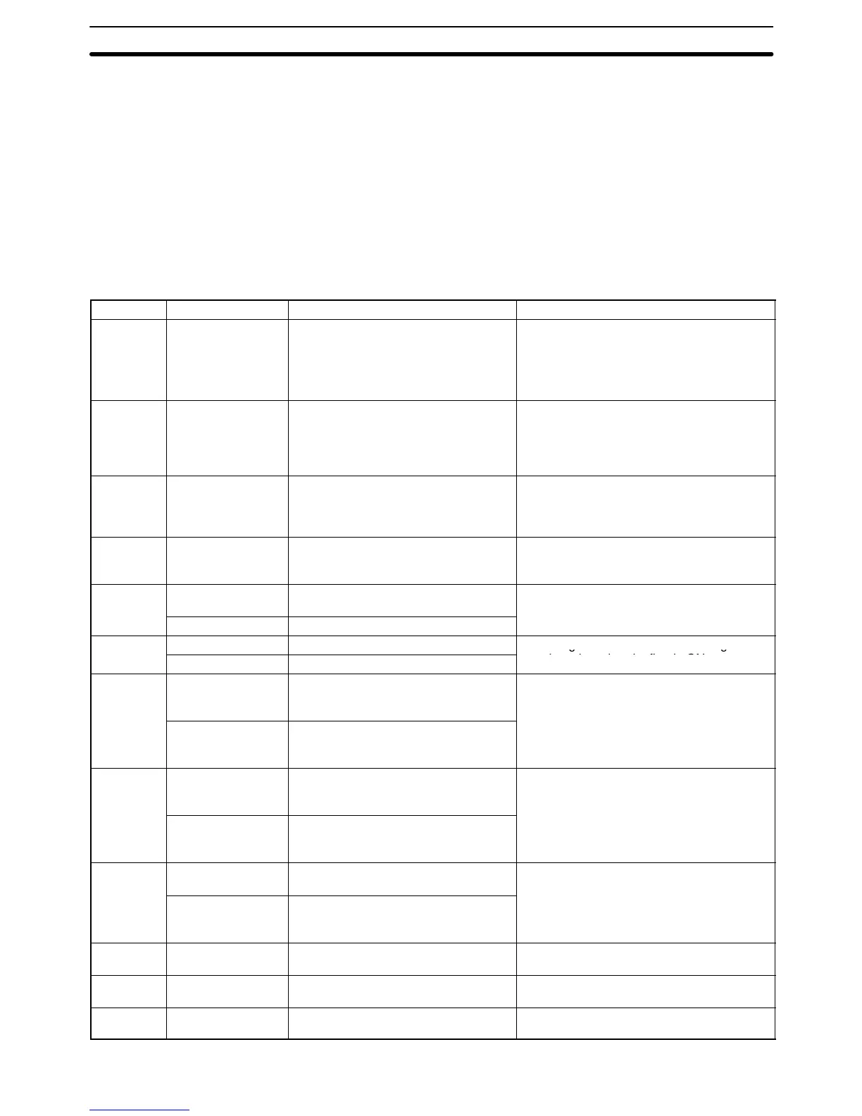
Details, including the name, range, and function of each area are summa-
rized in the following table. The PC memory addresses are shown in paren-
theses. These memory address are used for indirect addressing. Refer to
3-11 DM and EM Areas
and to
5-3 Data Areas, Definers, and Flags
for de-
tails on indirect addressing.
Area PC Range Function
CIO Area
(Core I/O)
All Words: CIO 0000 to CIO 2555
Bits: CIO 000000 to CIO 255515
($0000 to $09FB)
The CIO (Core I/O) Area is divided into
eight sections, five controlling I/O and three
used to store and manipulate data
internally.
Refer to
3-3 CIO (Core I/O) Area
for details.
Temporary
Relay Area
All TR0 to TR7 (bits only)
($09FF)
Used to temporarily store execution
conditions. TR bits are not input when
programming directly in ladder diagrams,
and are used only when programming in
mnemonic form.
CPU Bus
Link Area
All Words: G000 to G255
Bits: G00000 to G25515
($0A00 to $0AFF)
G000 is the PC Status Area; G001 to G004,
the Clock Area. G008 to G127 contain PC
output bits; G128 to G255, CPU Bus Unit
output bits.
Auxiliary
Area
All Words: A000 to A511
Bits: A00000 to A51115
($0B00 to $0CFF)
Contains flags and bits with special
functions.
Transition
Area
CV500 TN0000 to TN0511
($0D00 to $0D1F)
Transition Flags for the transitions in the
SFC program.
CV1000/CV2000 TN0000 to TN1023 ($0D00 to $0D3F)
Step Area CV500 ST0000 to ST0511 ($0E00 to $0E1F) Step Flags for steps in the SFC program. A
step is active when its flag is ON.
Timer Area CV500/
CVM1-CPU01-EV2
T0000 to T0511
(Completion Flags: $0F00 to $0F1F
Present Values: $1000 to $11FF)
Used to define timers (normal, high-speed,
and totalizing) and to access Completion
Flags, PV, and SV.
CV1000/CV2000/
CVM1-CPU11-EV2
CVM1-CPU21-EV2
T0000 to T1023
(Completion Flags: $0F00 to $0F3F
Present Values: $1000 to $13FF)
Counter
Area
CV500/
CVM1-CPU01-EV2
C0000 to C0511
(Completion Flags: $0F80 to $0F9F
Present Values: $1800 to $19FF)
Used to define counters (normal, reversible,
and transition) and to access Completion
Flags, PV, and SV.
CV1000/CV2000/
CVM1-CPU11-EV2
CVM1-CPU21-EV2
C0000 to C1023
(Completion Flags: $0F80 to $0FBF
Present Values: $1800 to $1BFF)
DM Area CV500/
CVM1-CPU01-EV2
D00000 to D08191 ($2000 to $3FFF) Used for internal data storage and
manipulation.
CV1000/CV2000/
CVM1-CPU11-EV2
CVM1-CPU21-EV2
D00000 to D24575 ($2000 to $7FFF)
EM Area CV1000/CV2000
CVM1-CPU21-EV2
E00000 to E32765 for each bank; 2,
4, or 8 banks ($8000 to $8FFD)
EM functions just like DM. An Extended
Data Memory Unit must be installed.
Index
registers
All IR0 to IR2 Used for indirect addressing.
Data
registers
All DR0 to DR2 Generally used for indirect addressing.
Introduction Section 3-1