36
Some data areas contain flags and/or control bits. Flags are bits that are au-
tomatically turned ON and OFF to indicate particular operation status. Al-
though some flags (e.g., the Carry Flag) can be turned ON and OFF by the
user, most flags are read only; they cannot be controlled directly.
Control bits are bits turned ON and OFF by the user to control specific as-
pects of operation. Any bit given a name using the word bit rather than the
word flag is a control bit, e.g., Restart Bits are control bits.
3-2 Data Area Structure
Addresses There are two different sets of addresses that can be used to access PC
memory: data area addresses or memory addresses. Data area addresses are
used when specifying an address directly as an operand for an instruction.
Memory addresses are used when using indirect addressing.
When designating a data area address, the acronym for the area (the let-
ter(s) identifying the data area) is always required for any area except the
CIO (Core I/O) Area. Although the CIO acronym is given for clarity in text ex-
planations, it is not required and not entered when programming.
It is possible also to access any memory location through its hexadecimal PC
memory address with indirect addressing. Refer to
3-11 DM and EM Areas
,
and
3-12 IR and DR Areas
, for details on indirect addressing.
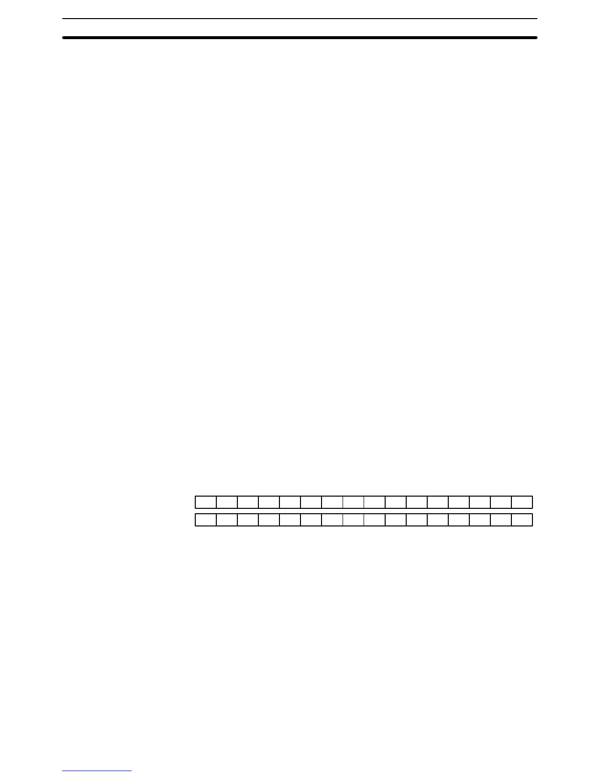
Word Structure Memory areas are divided up into words, each of which consists of 16 bits num-
bered 00 through 15 from right (least significant) to left (most significant). CIO
words 0000 and 0001 are shown below with bit numbers. Here, the content of
each word is shown as all zeros. Bit 00 is called the rightmost bit; bit 15, the left-
most bit.
The term least significant bit is often used for rightmost bit; the term most
significant bit, for leftmost bit.
Bit number
CIO word 0000 0000000000000000
CIO word 0001 0000000000000000
15 14 13 12 11 10 09 08 07 06 05 04 03 02 01 00
Data in the DM Area and EM Area, as well as Timer and Counter PVs can be
accessed as words only. Transition Flags, Step Flags, and Timer and Count-
er Completion Flags can be accessed as bits only. You cannot designate any
of these for operands requiring bit data. Data in the CIO, CPU Bus Link, and
Auxiliary Areas is accessible either by word or by bit, depending on the
instruction in which the data is being used.
To designate one of these areas by word, all that is necessary is the acro-
nym, if required, and the two-, three-, or four-digit word address. To desig-
nate an area by bit, the word address is combined with the bit number as a
single four- to six-digit address. The following table shows examples of this.
The two rightmost digits of a bit address must indicate a bit between 00 and
15, e.g., the rightmost digit must be 5 or less when the next digit to the left
is 1.
Flags and Control Bits
Data Area Structure Section 3-2