47
either a SYSMAC LINK System or a SYSMAC NET Link System. Link Area
addresses run from CIO 1000 through CIO 1199. Link Area words CIO 1000
through CIO 1063 and DM Area words D00000 through D00127 are auto-
matically used for data link tables unless specific link words are designated.
Allocations can be designated from the CVSS/SSS. Refer to the
CVSS/SSS
Operation Manuals
, and the
SYSMAC LINK System Manual
, or
SYSMAC
NET Link System Manual
for details.
3-3-5 Holding Area
The Holding Area is used to store/manipulate various kinds of data and can
be accessed either by word or by bit. Holding Area bits can be used in any
order required and can be programmed as often as required.
The default Holding Area word addresses range from CIO 1200 through CIO
1499; bit addresses, from CIO 120000 through CIO 149915. The range of the
Holding Area can be changed to any size between CIO 1000 through CIO
2399 with the PC Setup from the CVSS/SSS. If the Holding Area is in-
creased, it will overlap other areas. An “H” will appear before Holding Area bit
addresses on the CVSS/SSS screen. Refer to the
CVSS/SSS Operation
Manuals
for details.
The Holding Area retains status when the operating mode is changed, power
is interrupted, or PC operation is stopped.
Holding Area bits and words can be used to preserve data whenever PC op-
eration is stopped. Holding bits also have various special applications, such
as creating latching relays with the KEEP instruction and forming self-holding
outputs. These are discussed in
Section 4 Writing Programs
and
Section 5
Instruction Set
.
3-3-6 CPU Bus Unit Area
Two types of external bus are provided for CV-series PCs: the high-speed CPU
bus (S Bus) and the I/O bus. Units that connect to the CPU bus on the CPU or
Expansion CPU Rack are called CPU Bus Units and include the SYSMAC NET
Link Unit, SYSMAC LINK Unit, SYSMAC BUS/2 Remote I/O Master Unit, BASIC
Unit, and Personal Computer Unit.
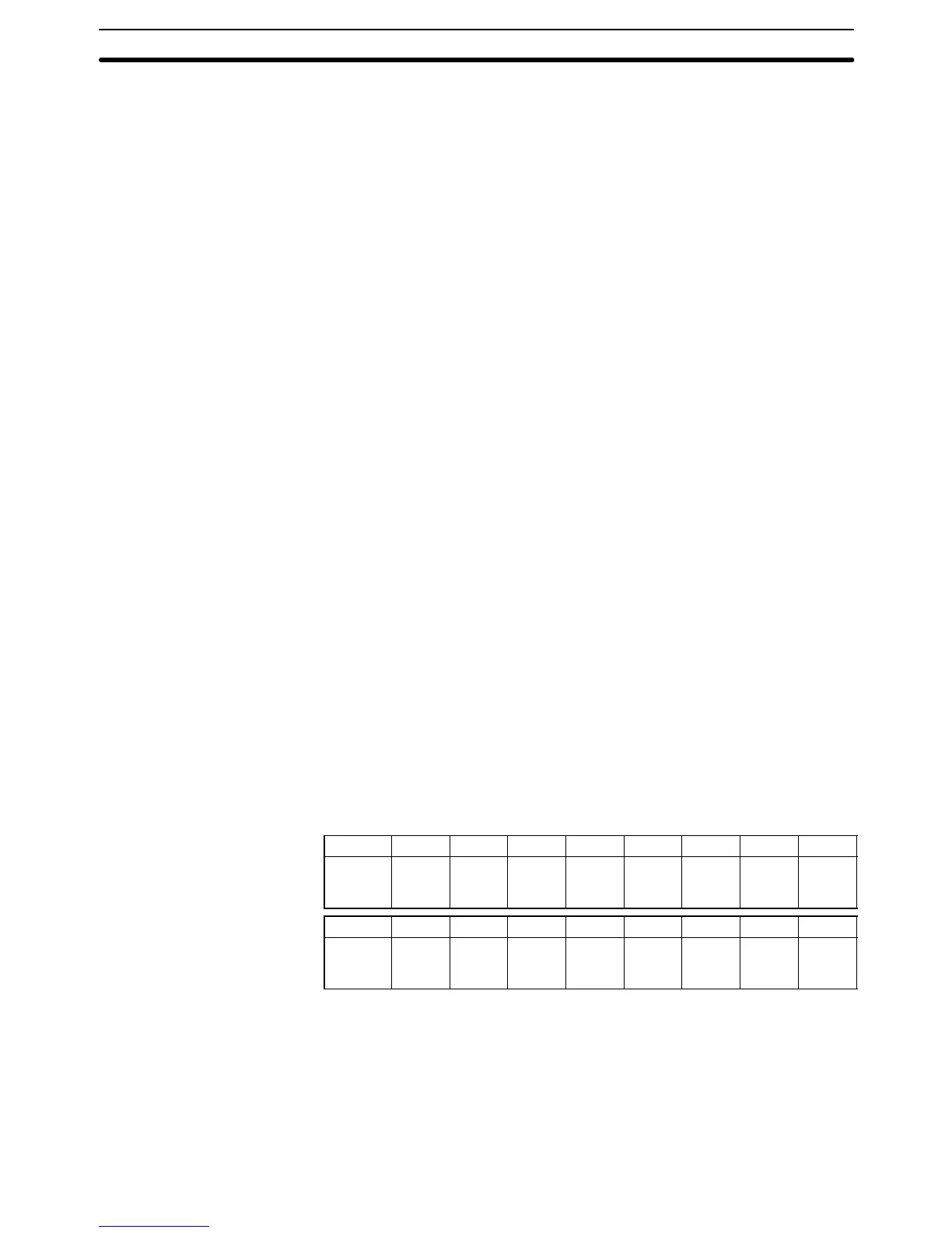
CPU Bus Unit Area addresses range from CIO 1500 through CIO 1899. These
400 words are divided into 16 groups of 25 words each. These are allocated to
CPU Bus Units according their unit number settings as shown in the following
tables.
Unit # 0 1 2 3 4 5 6 7
CIO
words
1500
to
1524
1525
to
1549
1550
to
1574
1575
to
1599
1600
to
1624
1625
to
1649
1650
to
1674
1675
to
1699
Unit # 8 9 10 11 12 13 14 15
CIO
words
1700
to
1724
1725
to
1749
1750
to
1774
1775
to
1799
1800
to
1824
1825
to
1849
1850
to
1874
1875
to
1899
An additional1600 words in the DM Area (D02000 to D03599) are provided for
CPU Bus Units. The particular function of words allocated to the Unit depends on
the CPU Bus Unit being used.
3-3-7 CompoBus/D Areas
I/O bits allocated to CompoBus/D correspond to external I/O points on the de-
vices connected to the CompoBus/D device network. Refer to
CompoBus/D
(DeviceNet) Operation Manual
(W267) for further information.
CIO (Core I/O) Area Section 3-3