EasyManua.ls Logo

Omron SYSMAC CV Series User Manual

Omron SYSMAC CV Series
636 pages
To Next Page IconTo Next Page
To Previous Page IconTo Previous Page
Page #481 background imageLoading...
Page #481 background image
470
The following CVSS/SSS operations are instruction execution events:
Monitoring, data modification, set, reset, online edit, DM edit, search,
transfer block (CVSS/SSS to PC), save block (CVSS/SSS to PC), I/O table
change, PC Setup, PC Setup information transfer, data trace execution,
program trace execution, setting program memory protect, clearing
program memory protect, Memory Card (program, I/O memory)
The following host interface operations are writing events:
Data area block write, data area transfer, parameter area write, parameter
area block write, start program area protect, clear protect area, program
area read, program area write, program area clear, cycle time read, program
area to file transfer, force set/reset, force set/reset for all bits
When SFC online editing is selected from the CVSS, all writing events will be
suspended until the online editing has been completed.
6-3 Calculating Cycle Time
The PC configuration, the program, and program execution conditions must
be taken into consideration when calculating the cycle time. This means tak-
ing into account such things as the number of I/O points, the programming
instructions used, and whether or not Peripheral Devices are being used.
This section shows a basic example of cycle time calculation. Operating
times are given in the tables in
6-2 Cycle Time
.
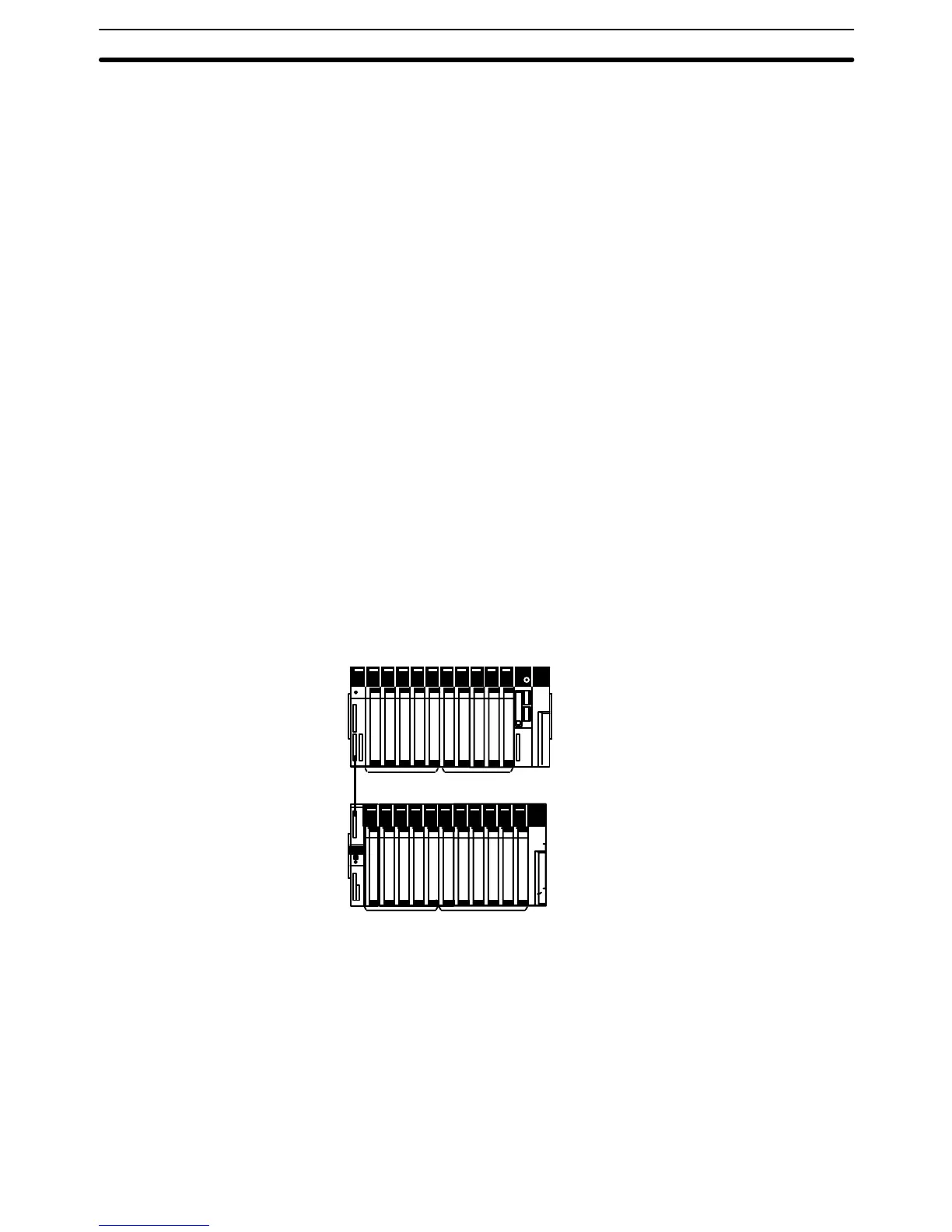
Here, we’ll compute the cycle time for a CV1000 or CV2000 set for cyclic re-
freshing. The PC controls only I/O Units, ten on the CPU Rack and eleven on
an Expansion I/O Rack. The PC configuration for this is shown below. It is
assumed that the program contains 20,000 instructions requiring an average
of 0.3 µs each to execute.
Refer to the next section for instruction execution times. Using the cycle time
in calculating the I/O response time is described in the last part of
Section 6
.
32-point Output Units
16-point Input
Units
32-point Input Units
16-point Output
Units
CPU Rack
Expansion I/O
Rack
The equation for the cycle time from above is as follows:
Cycle time = overseeing time (basic processes)
+ program execution
+ output refreshing
+ input refreshing time
The overseeing time is fixed at 0.5 ms for nonsynchronous processing.
The program execution time is 6 ms (0.3 µs/instruction times 20,000 instruc-
tions).
SFC Online Editing
Calculations
Calculating Cycle Time Section 6-3

Table of Contents

Question and Answer IconNeed help?

Do you have a question about the Omron SYSMAC CV Series and is the answer not in the manual?

Omron SYSMAC CV Series Specifications

General IconGeneral
SeriesSYSMAC CV Series
TypePLC
Input Voltage100 to 240 VAC, 24 VDC
Number of InputsVaries by model
Number of OutputsVaries by model
I/O CapacityUp to 2048 points
I/O PointsVaries by model
Communication PortsRS-232C, RS-422/485
Programming LanguageLadder Logic
Power Supply100-240V AC or 24V DC
MountingDIN rail mounting
Operating Temperature0°C to 55°C

Summary

PRECAUTIONS

2 General Precautions

User must operate product per specifications; consult OMRON for non-manual conditions or critical systems.

3 Safety Precautions

Precautions regarding power supply, terminal touching, disassembly, repair, and battery handling.

4 Operating Environment Precautions

Guidelines for environmental conditions for PC system installation and operation.

5 Application Precautions

Precautions for safe PC system usage, grounding, power supply, wiring, and program changes.

SECTION 1 Introduction

SECTION 2 Hardware Considerations

2-3 Memory Cards

Covers file memory used to store programs and other data, including RAM, EPROM, and EEPROM types.

2-7 PC Configuration

Provides an overview of the PC configuration, including CPU Rack, Expansion CPU Rack, and Expansion I/O Rack.

SECTION 3 Memory Areas

3-2 Data Area Structure

Describes two sets of addresses for accessing PC memory: data area addresses and memory addresses.

3-3 CIO (Core I/O) Area

Details CIO Area addresses, divided into eight data areas for I/O control and internal data manipulation.

3-6 Auxiliary Area

Contains flags and control bits for monitoring and controlling PC operation, accessing clock pulses, and signaling errors.

SECTION 4 Writing Programs

4-1 Basic Procedure

Outlines basic steps for writing a program, including I/O device list and work bit allocation.

4-3 Basic Ladder Diagrams

Describes ladder diagrams, which consist of vertical lines (bus bars) and branching lines (instruction lines or rungs).

4-7 Controlling Bit Status

Lists instructions used to control individual bit status, such as OUTPUT, SET, RESET, and KEEP.

4-10 Programming Precautions

Provides guidelines on programming practices, such as unlimited conditions in series or parallel and avoiding vertical conditions.

SECTION 5 Instruction Set

5-6 Ladder Diagram Instructions

Covers instructions that correspond to ladder diagram conditions and logic block instructions for complex relationships.

5-7 Bit Control Instructions

Explains instructions used to control bit status by turning bits ON and OFF in different ways.

5-13 Timer and Counter Instructions

Details instructions for creating timers and counters, accessing PVs and Completion Flags.

5-15 Data Movement Instructions

Explains instructions used for moving data between different addresses in data areas.

5-16 Comparison Instructions

Covers instructions used for comparing data, affecting comparison flags and outputting results.

5-17 Conversion Instructions

Explains instructions that convert word data from one format to another, outputting converted data to specified result words.

SECTION 6 Program Execution Timing

6-2 Cycle Time

Explains operations affecting cycle time and I/O response time, and shows basic cycle time calculation.

6-5 I/O Response Time

Explains the time taken for the PC to output a control signal after receiving an input signal.

SECTION 7 PC Setup

SECTION 8 Error Processing

8-4 Error Messages

Classifies errors into initialization, non-fatal operating, and fatal operating errors for message display.

Appendices

A Instruction Set

Details all ladder diagram programming instructions, variations, and applicable data areas.

B Error and Arithmetic Flag Operation

Explains instructions affecting ER, CY, GR, LE, EQ, OF, UF, and N flags.

C PC Setup Default Settings

Lists default values for PC Setup parameters.

D Data Areas

Summarizes data areas in CV-series PCs, including CIO, Temporary Relay, and Auxiliary Areas.

Related product manuals