2
1-1 Overview
A PC (Programmable Controller) is basically a CPU (Central Processing Unit)
containing a program and connected to input and output (I/O) devices. The pro-
gram controls the PC so that when an input signal from an input device turns ON
or OFF, the appropriate response is made. The response normally involves turn-
ing ON or OFF an output signal to some sort of output device. The input devices
could be photoelectric sensors, pushbuttons on control panels, limit switches, or
any other device that can produce a signal that can be input into the PC. The
output devices could be solenoids, indicator lamps, relays turning on motors, or
any other devices that can be activated by signals output from the PC.
For example, a sensor detecting a passing product turns ON an input to the PC.
The PC responds by turning ON an output that activates a pusher that pushes
the product onto another conveyor for further processing. Another sensor, posi-
tioned higher than the first, turns ON a different input to indicate that the product
is too tall. The PC responds by turning on another pusher positioned before the
pusher mentioned above to push the too-tall product into a rejection box.
Although this example involves only two inputs and two outputs, it is typical of the
type of control operation that PCs can achieve. Actually even this example is
much more complex than it may at first appear because of the timing that would
be required, i.e., “How does the PC know when to activate each pusher?” Much
more complicated operations are also possible.
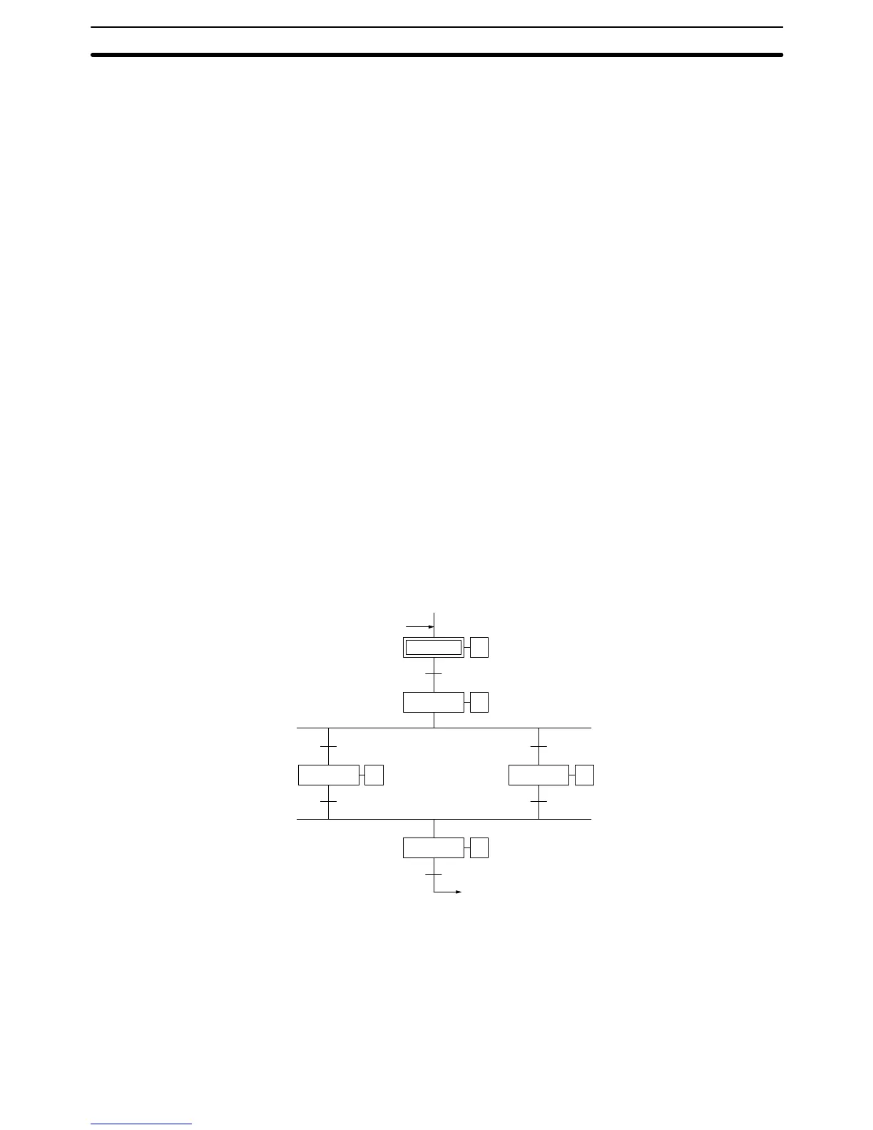
To achieve proper control, CV-series PCs use a form of PC logic called ladder-
diagram programming. A single ladder-diagram program can be used, as in C-
series PCs, but CV-series PCs are also support sequential function chart, or
SFC, programming. SFC programming breaks the program into sections based
on processes, greatly reducing program development and maintenance times,
and allowing program sections to be easily used in other programs. The follow-
ing diagram shows a simple SFC program, which consists of steps connected by
lines representing the flow of execution.
ST0000 01
TN0000
ST0001 02
000100
ST0011 02
000101
000200
ST0012 03
000201
ST0000
ST0020 00
000300
Initial step
Transition
Step
The transitions between the steps control when execution moves between the
steps and actions contained within the steps specify the actual executable ele-
ments of the program. Programming the actions and transitions within SFC pro-
gramming are generally achieved using ladder diagrams. There are also some
ladder diagram instructions that can be used to control the SFC program.
This manual is written to explain ladder-diagram programming and to prepare
the reader to program and operate the CV-series PCs. SFC programming is ex-
plained in the
CV-series PCs Operation Manual: SFC
.
Overview Section 1-1