23
2-1-2 Switches
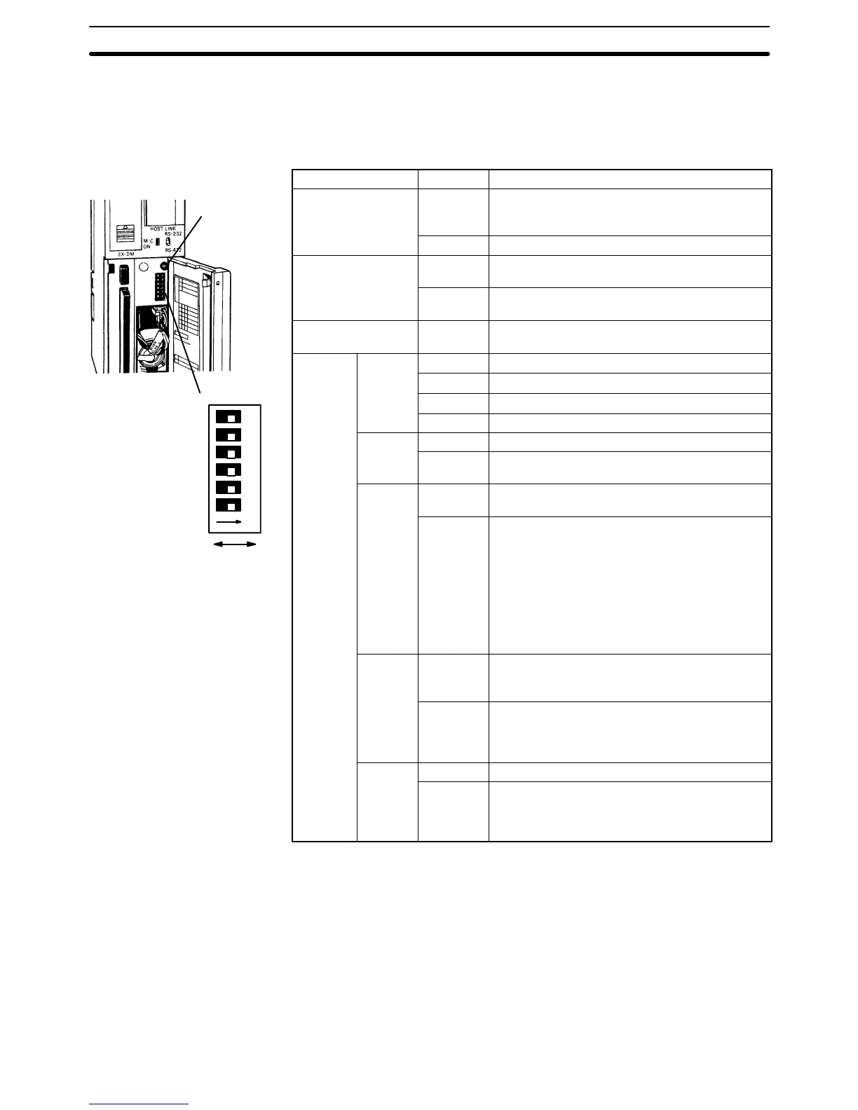
The DIP switch and memory card power switch are shown below and the setting
of these and the other CPU switches are described in the following table.
Switches are the same for all CV-series PCs.
Switch Position Function
Protect keyswitch Vertical Program Memory (i.e., the Extended PC Setup
and the user program) is write-protected.
(See note 1)
Horizontal Program Memory is not write-protected.
RS-422/RS-232C
selector
Up Host link communications set for RS-232.
(Also see CPU DIP switch pins 4 and 6 below.)
Down Host link communications set for RS-422.
(Also see CPU DIP switch pins 4 and 6 below.)
Memory Card power
switch (See note 4.)
Not
applicable
Press and release to turn the power on or off.
(The M/C ON indicator lights when power is on.)
CPU DIP
Pins 1, 2
and 4.)
OFF, ON Peripheral device communications: 9,600 bps
ON, ON Peripheral device communications: 4,800 bps
Pin 3
OFF Communicate via Host Link communications
ON Communicate with PT via NT Link communica-
tions.
Pin 4 OFF Host link communications governed by PC Set-
up. (See note 2)
ON Following settings used for host link communica-
tions, regardless of PC Setup: 9,600 bps, unit
number 00, even parity, 7-bit data, 2 stop bits.
Note: The above settings apply to CPUs
manufactured from July 1995 (lot number **75
for July 1995). For CPUs manufactured before
July 1995 (lot number **65 for June 1995), only
1 stop bit will be set and the baud rate will be
2,400 bps.
Pin 5
(See
note 4.)
OFF Files are not transferred from the Memory Card
automatically at start-up.
ON The program file (AUTOEXEC.OBJ) and PC
Setup file (AUTOEXEC.STD) will be transferred
from the Memory Card to the CPU automatically
at start-up.
Pin 6 OFF The termination resistance is off.
ON The termination resistance is on.
(This setting is used for the last Unit in a RS-422
Host Link System only; intermediate Units must
be set to OFF.)
Note 1. The user program can also be protected from a Peripheral Device.
2. Factory settings are 9,600 bps, 7-bit data, even parity, and 2 stop bits.
3. The baud rate must be set to 50,000 bps when the Graphic Programming
Console or Programming Console is connected to the PC, and to 9,600 bps
when a computer running the CV Support Software is connected.
4. The following switches and pins are also used for the simplified backup
function. Pins 1 and 2 are used to specify files, pin 5 is used to specify the
direction of the transfer, and the Memory Card power switch is used to start
data transfers. Refer to
1-13-4 Upgraded Specifications
for details.
CPU Components Section 2-1
OFF ON
123456ON
Memory Card
power switch
DIP switch