29
current bank number can be changed with the EMBC(171) instruction. Refer to
Section 5 Instruction Set
for details.
There are three models of EM Units available, as shown in the following table.
Model Memory capacity Memory banks
CV1000-DM641 64K words 2 (0 and 1)
CV1000-DM151 128K words 4 (0 to 3)
CV1000-DM251 256K words 8 (0 to 7)
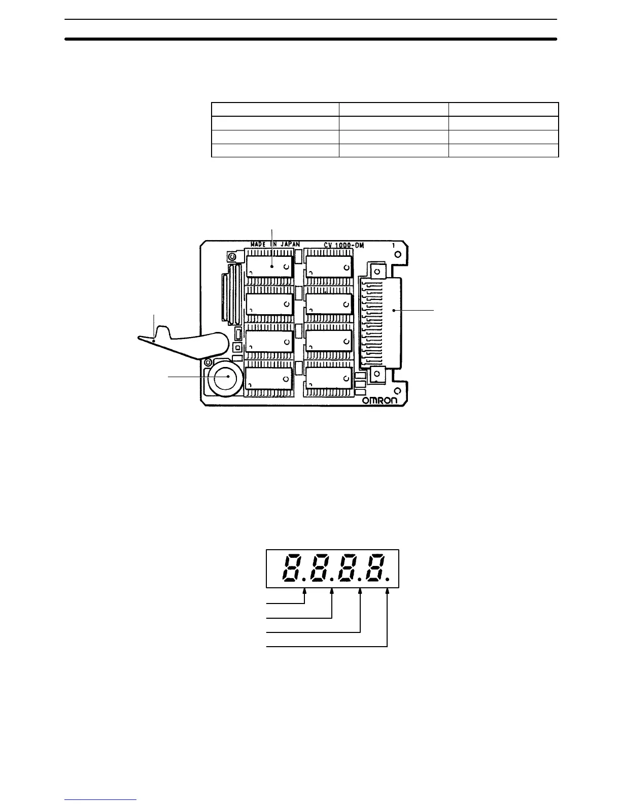
The following diagram shows the structure of the EM Unit and identifies its main
components.
Memory element
Pullout
lever
Backup
capacitor
Expansion Data Memory Unit
CPU
connector
2-5 I/O Control Unit and I/O Interface Unit Displays
The I/O Control Unit and I/O Interface Unit have four-character 7-segment dis-
plays on the front. There are four display modes that display various information
from the CPU, and the current display mode is indicated by the position of the
decimal point on the display, as shown in the following diagram.
Lit in mode 1
Lit in mode 2
Lit in mode 3
Lit in mode 4
Pressing the mode selector switch changes the display to the next mode. The
Unit will automatically enter the mode specified in the PC Setup (default setting:
mode 1). Refer to
Section 7 PC Setup
for details.
If the CPU Rack power supply is OFF or an initialization error has occurred, the
displays will show “––––” and the rack number will be displayed when the mode
selector switch is held down, but the mode will not be changed.
I/O Control Unit and I/O Interface Unit Displays Section 2-5