30
In mode 1, the first I/O word allocated to that Rack is displayed. If the I/O table
hasn’t been registered yet, or an error occurred during registration, the display
will show “0000.” In the following example, the first word allocated is CIO 0036.
16-
pt.
I/O
Word
36
Indicates mode 1
Word
37
Word
38
16-
pt.
I/O
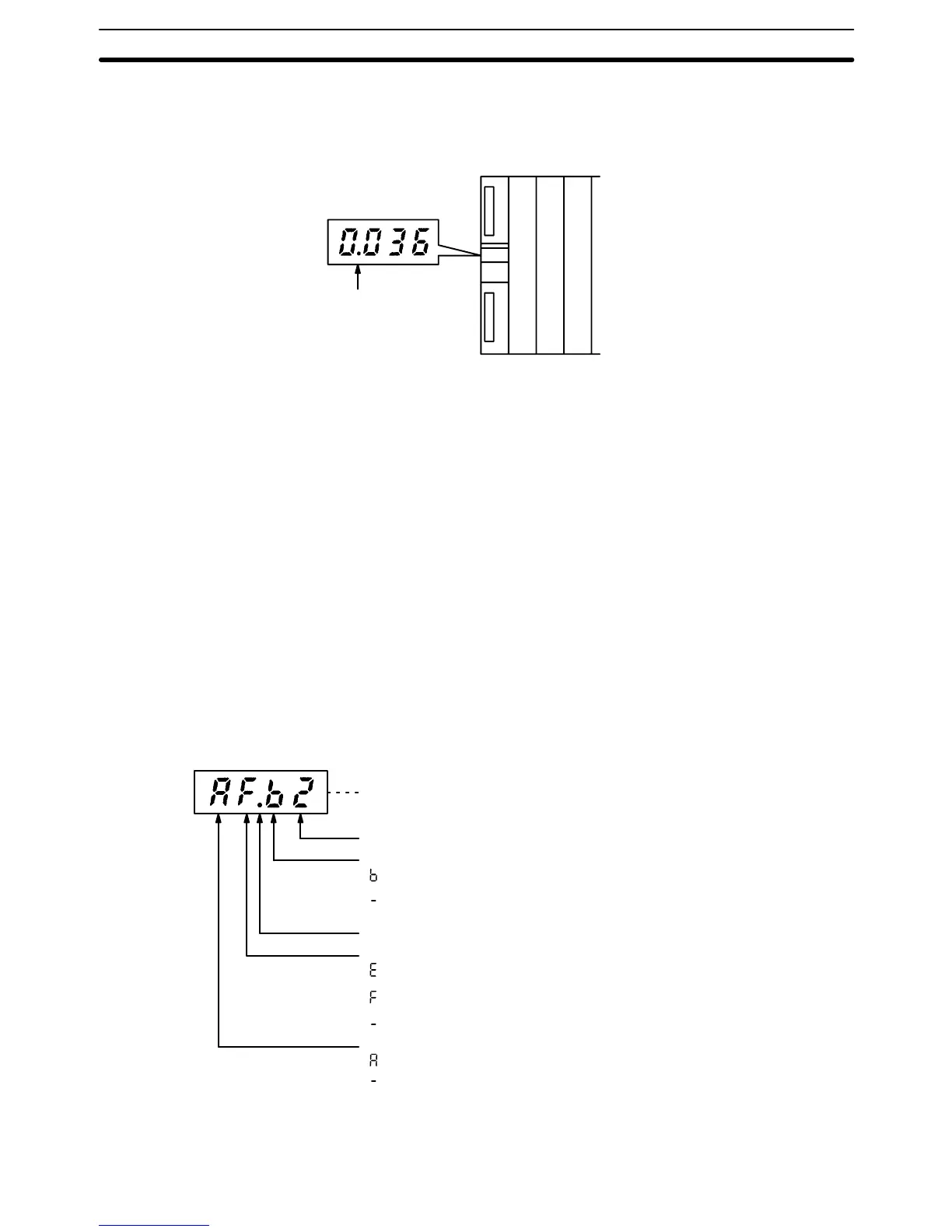
In mode 2, the current CPU status and the rack number of that Rack are dis-
played. The information displayed by the four digits is listed below.
1, 2, 3...
1. The leftmost digit indicates whether or not the CPU is operating.
“a” indicates it is operating.
“” indicates it is stopped.
2. The second digit indicates whether or not an error has occurred in the PC.
“e” indicates that a fatal error has occurred.
“f” indicates that a non-fatal error has occurred.
“” indicates that no errors have occurred.
3. The third digit from the left indicates whether or not a peripheral device is
connected to the CPU or Expansion CPU Rack. If a peripheral device is al-
ready connected, another cannot be connected.
“b” indicates that a peripheral device is connected.
“” indicates that a peripheral device is not connected.
Note Only one Peripheral Device can be connected to the CPU and I/O In-
terface Units for each PC, but three additional Peripheral Devices
can be connected to the SYSMAC BUS/2 Slave Racks.
4. The rightmost digit indicates the rack number.
Indicates the CPU is in the RUN mode, a non-fatal error has occurred,
a Peripheral Device is connected, and the rack number is 2.
Indicates the rack number
Indicates whether or not Peripheral Devices are connected.
: A Peripheral Device is connected to the CPU or to an I/O Inter-
face Unit.
: No Peripheral Device is connected to the CPU or to an I/O Inter-
face Unit.
Indicates mode 2
Indicates the error status of the CPU.
: A fatal error has occurred.
: A non-fatal error has occurred.
: No error has occurred.
Indicates the operating status of the CPU.
: The CPU is operating.
: The CPU has stopped.
In mode 3, the display shows a 4-character message when an IODP(189)
instruction is executed in the program for that Unit. The display mode of the des-
Display Mode 1
Display Mode 2
Display Mode 3
I/O Control Unit and I/O Interface Unit Displays Section 2-5