501
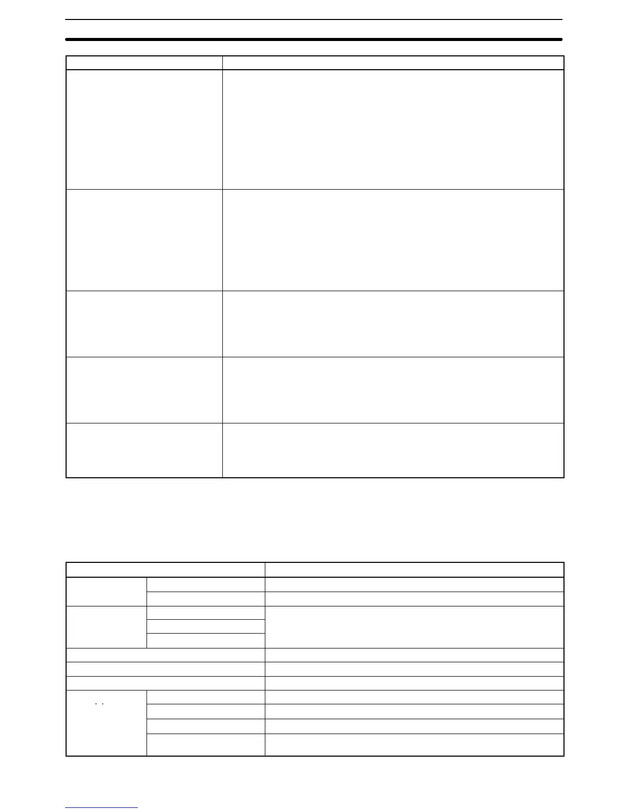
Name Operation
P:Power break Designate the momentary power interruption time between 0 and 9 ms.
Operation will continue for momentary power interruptions if the power supply is
restored within this time after a power interruption.
If the momentary power interruption time is greater than 0 ms, Peripheral Device
and Host Link communications may be disrupted and may go on standby for
momentary power interruptions.
This setting will be ignored and the default value will be used if a C500 Expansion
I/O Rack is connected to the System.
Changes to this setting are effective immediately.
(Default: 0 ms)
Q:Cycle time Set the minimum cycle time to between 0 and 32,000 ms. If the actual cycle time
is less than the set cycle time, execution will be halted until the set cycle time
elapses before the next cycle is executed. If the actual cycle time exceeds the set
cycle time, the setting is ignored and the next cycle is executed when the current
cycle is complete. Changes to this setting are effective immediately.
The actual cycle time might vary 3 to 4 ms from the set cycle time. If an interrupt
program is executed, the actual cycle time might be extended by the additional
time it takes to execute the interrupt program.
(Default: Variable cycle)
R:Watch cycle time Designate the maximum cycle time between 10 and 40,000 ms. If the cycle time
exceeds the designated value, a fatal error will occur and A40108 will be turned
ON (Cycle Time Too Long Flag). The actual maximum cycle time might vary
about 5 ms from the designated value.
Changes to this setting are effective immediately.
(Default: 1,000 ms)
S:Error log Designate the size and range of the error log area. When a error occurs,
information about the error is saved in this memory area together with the time
that the error occurred. The error log can be allocated in the DM or EM Area. Up
to 2,047 errors can be recorded.
Changes to this setting are effective the next time the power is turned ON.
(Default: 20 records of 5 words each in A100 to A199)
T:IOIF, RT display Designate the display mode to be used for the 7-segment displays on I/O
Interface Units, the I/O Control Unit, and SYSMAC BUS/2 Remote I/O Slave
Units when the power is turned ON.
Changes to this setting are effective the next time the power is turned ON.
(Default: Mode 1)
7-3 PC Setup Default Settings
Parameter Default value
A:Hold areas H:Hold areas CIO 1200 to CIO 1499
R:Hold bits Nothing held.
B:Startup hold K:Forced Status
Reset at startup.
I:I/O bits
D:Power on flag
C:Startup mode PROGRAM
D:Startup processing Don’t transfer program.
E:I/O refresh Cyclic refreshing
F:Execute