301
UF (A50010): Absolute value of the result is less than the minimum value
that can be expressed for floating-point data.
5-21-7 FLOATING-POINT MULTIPLY: *F(456)
(456)
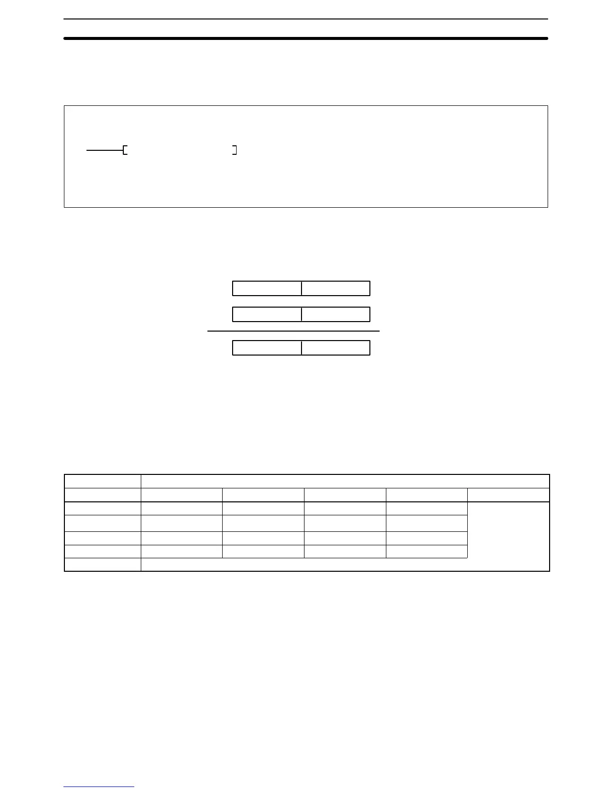
*FMdMrR
Ladder Symbol
Variations
↑*F(456)
Operand Data Areas
Md: First multiplicand word CIO, G, A, T, C, #, DM
R: First result word CIO, G, A, DM
Mr: First multiplier word CIO, G, A, T, C, #, DM
When the execution condition OFF, *F(456) is not executed. When the execu-
tion condition is ON, *F(456) multiplies the 32-bit floating-point content of Md
and Md +1 by the 32-bit floating-point content of Mr and Mr +1 and places the
result in R and R+1.
R+1 R
Md Multiplicand (floating-point data, 32 bits)
Md+1
Mr Multiplier (floating-point data, 32 bits)
Mr+1
Result (floating-point data, 32 bits)
x
If the absolute value of the result is greater than the maximum value that can be
expressed for floating-point data, the Overflow Flag (A50009) will turn ON and
the result will be output as ±.
If the absolute value of the result is less than the minimum value that can be ex-
pressed for floating-point data, the Underflow Flag (A50010) will turn ON and the
result will be output as 0.
The various combinations of multiplicand and multiplier data will produce the re-
sults shown in the following table.
Multiplicand
Multiplier 0 Numeral + – NaN
0 0 0 ER ER
Numeral 0
See
note
1.
+/– +/–
+ ER +/– + –
– ER +/– – +
NaN
ER
Note 1. The results could be zero (including underflows), a numeral, +, or –.
2. ER: The Error Flag (A50003) turns ON and the instruction is not executed.
Precautions Md, Md+1, Mr, and Mr+1 must be floating-point data.
Note Refer to page 115 for general precautions on operand data areas.
Flags ER (A50003): Md, Md+1, Mr, and Mr+1 are not floating-point data.
The content of a*DM word is not BCD when set for BCD.
EQ (A50006): The exponent and mantissa of the result are 0.
N (A50008): The result is a negative number.
OF (A50009): The absolute value of the result is greater than the maximum
value that can be expressed for floating-point data.
Description
(CVM1 V2)
Floating-point Math Instructions
Section 5-21