!
66
Note Do not use A50015 to control execution of differentiated instructions. The
instructions will never be executed.
3-6-54 Clock Pulse Bits
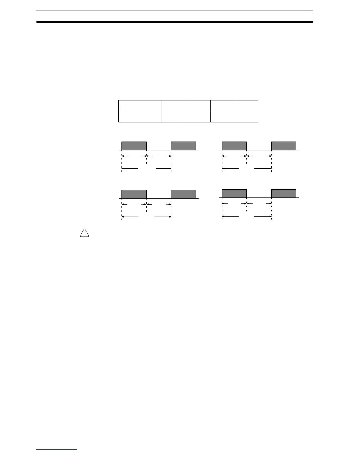
Four clock pulses are available to control program timing. Each clock pulse
bit is ON for the first half of the rated pulse time, then OFF for the second
half. In other words, each clock pulse has a duty factor of 50%.
These clock pulse bits are often used with counter instructions to create tim-
ers. Refer to
5-13 Timer and Counter Instructions
for an example of this.
Pulse width 0.1 s 0.2 s 1.0 s 0.02 s
Bit A50100 A50101 A50102 A50103
Bit A50103
0.02-s clock pulse
Bit A50100
0.1-s clock pulse
Bit A50101
0.2-s clock pulse
Bit A50102
1.0-s clock pulse
0.1 s
.05 s .05 s
1.0 s
0.5 s 0.5 s
0.2 s
0.1 s 0.1 s
0.02 s
.01 s .01 s
Caution Because the 0.1-second and 0.02-second clock pulse bits have ON times of 50
and 10 ms, respectively, the CPU may not be able to accurately read the pulses if
program execution time is too long.
3-6-55 Network Status Flags
Bits A50200 through A50207 are turned ON to indicate that ports #0 through
#7, respectively, are enabled for the SEND(192), RECV(193), and
CMND(194) in either a SYSMAC NET Link or SYSMAC LINK System. Bits
A50208 through A50215 are turned ON to indicate that an error has occurred
in ports #0 through #7, respectively, during data communications using
SEND(192), RECV(193), or CMND(194).
A503 through A510 contain the completion codes for ports #0 through #7, re-
spectively, following data communications using SEND(192), RECV(193), or
CMND(194). Refer to the
SYSMAC NET Link System Manual
or
SYSMAC LINK
System Manual
for details on completion codes.
3-6-56 EM Status Flags
The rightmost digit of A511 will contain the current bank number. Bit A51115 (the
EM Installed Flag) is turned ON when a EM Unit is mounted to the CPU.
3-7 Transition Area
A transition is a condition which moves the active status from one step to the next
in the SFC program. Flags in the Transition Area are turned ON when a
TOUT(202) instruction is executed with an ON execution condition, or a
TCNT(123) counter times out.
The CV500 has 512 Transition Flags, numbered TN0000 to TN0511, and the
CV1000 or CV2000 has 1,024 Transition Flags, numbered TN0000 to TN1023.
Transition Area Section 3-7