0005
01
T0001
0000
00
0000
01
0005
00
(015)
TIMH 0001 0020
(015)
TIMH 0000 #0150
1.5 s
T0000
CIO 0020
148
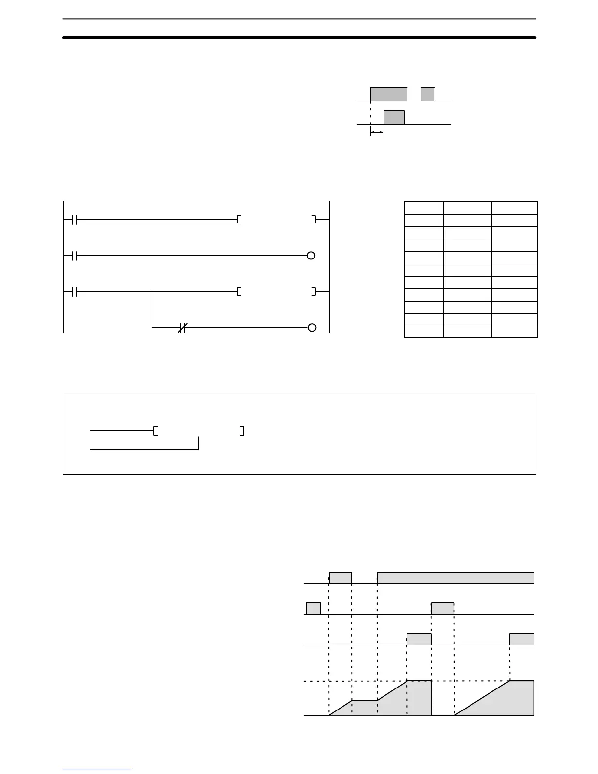
Example The following timing chart illustrates the operation of the first TIMH(015) in the
following example.
Completion Flag
000500
1.50 s
Timer input
000000
When CIO 000001 is ON, the SV for the second TIMH(015) in the following ex-
ample will be read from CIO 0020, allowing the SV of the timer to be control from
an external device connected through CIO 0020.
Address Instruction Operands
00000 LD 000000
00001 TIMH(015) 0000
#0150
00002 LD T0000
00003 OUT 000500
00004 LD 000001
00005 TIMH(015) 0001
00020
00006 AND NOT T0001
00007 OUT 000501
5-13-3 ACCUMULATIVE TIMER: TTIM(120)
(120)
TTIM N S
S: Set value CIO, G, A, T, C, #, DM, DR, IR
*Refer to page 141 for details on indirectly addressing timers.
N: Timer number #
Operand Data AreasLadder Symbol
I
R
Description A TTIM(120) timer is based on two execution conditions. These execution
conditions are labeled I and R. I is the timer input; R, the reset input. The timer PV
is clocked while the timer input is ON, maintained when I is OFF, and reset to
zero when R is ON. If both I and R are ON simultaneously, the timer is reset.
TTIM(120) increments in units of 0.1 second from zero. TTIM(120) accuracy is
+0.0/–0.1 second.
Timer input (I)
Reset input (R)
Completion Flag
(T0128)
Present value: 0100
0000
Timer and Counter Instructions Section 5-13