EasyManua.ls Logo

Omron SYSMAC CV Series User Manual

Omron SYSMAC CV Series
636 pages
To Next Page IconTo Next Page
To Previous Page IconTo Previous Page
Page #331 background imageLoading...
Page #331 background image
319
5-23 Special Math Instructions
The Special Math Instructions preform special arithmetic operations. MAX(165)
searches a range of words for the maximum value. MIN(166) searches a range
of words for the minimum value. SUM(167) adds a range of words. ROOT(140)
finds the square root of a value. FDIV(141) performs float-point division.
APR(142) finds the sine or cosine of an angle or extrapolates the Y value for a
given X value based on a table of coordinates.
5-23-1 FIND MAXIMUM: MAX(165)
Variations
j MAX(165)
(165)
MAX C R
1
D
R
1
: 1
st
word in range CIO, G, A, T, C, DM,
D: Destination word CIO, G, A, DM, DR, IR
C: Control word CIO, G, A, #, DM, DR, IR
Operand Data AreasLadder Symbol
When the execution condition is OFF, MAX(165) is not executed. When the ex-
ecution condition is ON, MAX(165) searches the range of memory from R
1
to
R
1
+N–1 for the address that contains the maximum value, outputs the maximum
value to the destination word (D) and, if bit 14 of C is ON, outputs the memory
address of the word containing the maximum value to IR0.
If bit 14 of C is ON and more than one address contains the same maximum val-
ue, the lowest of the addresses will be output to IR0.
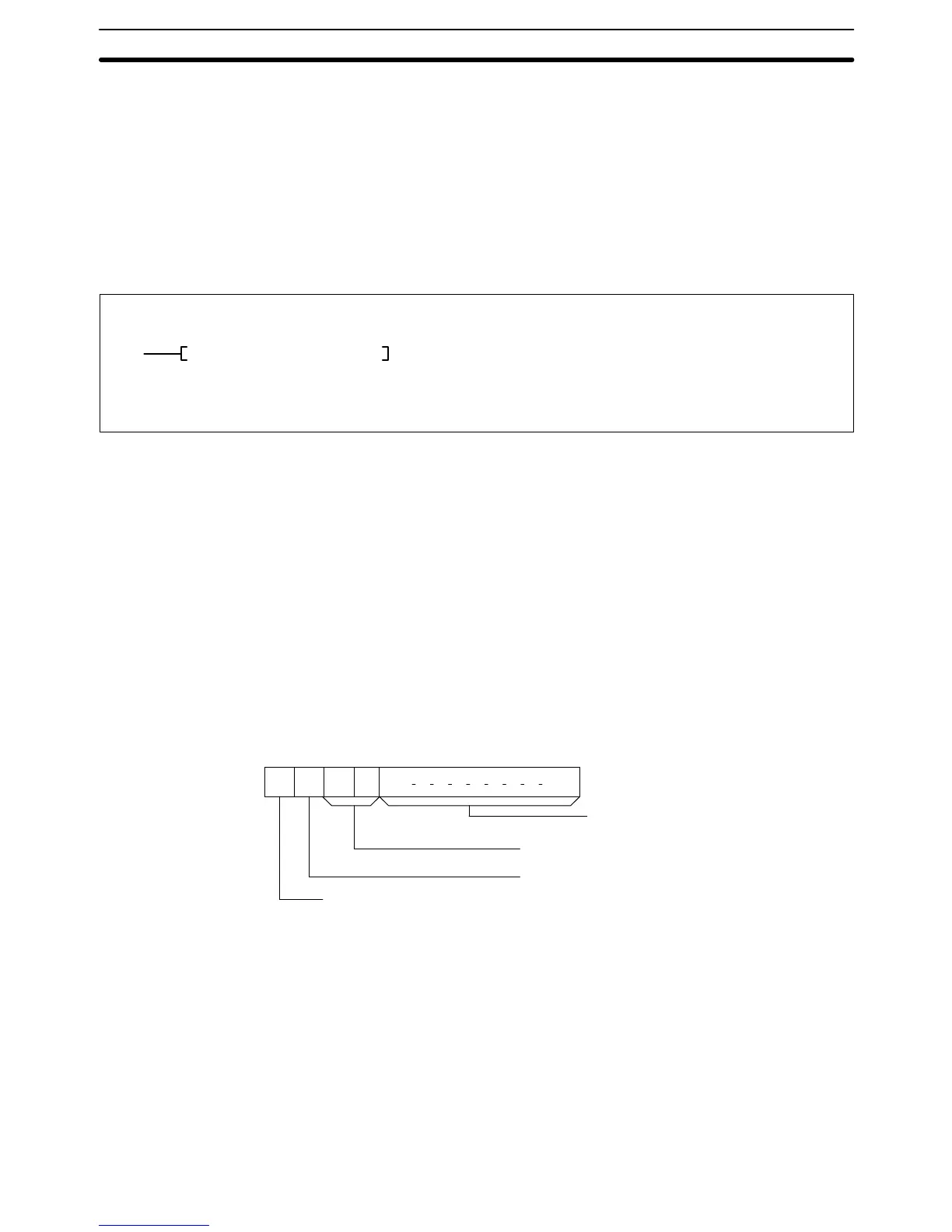
The number of words within the range (N) is contained in the 3 rightmost digits of
C, which must be BCD between 001 and 999.
When bit 15 of C is OFF, data within the range is treated as unsigned binary and
when it is ON the data is treated as signed binary. Refer to
3-2 Data Area Struc-
ture
for information on signed and unsigned binary data.
15 14 13 12 11 00
Output address to IR0
1 (ON): Yes.
0 (OFF): No.
Number of words
in range (N)
Not used – set to zero.
Data type
1 (ON): Signed binary
0 (OFF): Unsigned binary
C:
The 3 rightmost digits of C must be BCD between 001 and 999.
Note Refer to page 115 for general precautions on operand data areas.
Flags ER (A50003): The 3 rightmost digits of C are not BCD between 001 and 999.
Content of *DM word is not BCD when set for BCD.
EQ (A50006): The maximum value is zero.
N (A50008): Shows the status of bit 15 of the maximum value.
Description
Precautions
Special Math Instructions Section 5-23

Table of Contents

Question and Answer IconNeed help?

Do you have a question about the Omron SYSMAC CV Series and is the answer not in the manual?

Omron SYSMAC CV Series Specifications

General IconGeneral
SeriesSYSMAC CV Series
TypePLC
Input Voltage100 to 240 VAC, 24 VDC
Number of InputsVaries by model
Number of OutputsVaries by model
I/O CapacityUp to 2048 points
I/O PointsVaries by model
Communication PortsRS-232C, RS-422/485
Programming LanguageLadder Logic
Power Supply100-240V AC or 24V DC
MountingDIN rail mounting
Operating Temperature0°C to 55°C

Summary

PRECAUTIONS

2 General Precautions

User must operate product per specifications; consult OMRON for non-manual conditions or critical systems.

3 Safety Precautions

Precautions regarding power supply, terminal touching, disassembly, repair, and battery handling.

4 Operating Environment Precautions

Guidelines for environmental conditions for PC system installation and operation.

5 Application Precautions

Precautions for safe PC system usage, grounding, power supply, wiring, and program changes.

SECTION 1 Introduction

SECTION 2 Hardware Considerations

2-3 Memory Cards

Covers file memory used to store programs and other data, including RAM, EPROM, and EEPROM types.

2-7 PC Configuration

Provides an overview of the PC configuration, including CPU Rack, Expansion CPU Rack, and Expansion I/O Rack.

SECTION 3 Memory Areas

3-2 Data Area Structure

Describes two sets of addresses for accessing PC memory: data area addresses and memory addresses.

3-3 CIO (Core I/O) Area

Details CIO Area addresses, divided into eight data areas for I/O control and internal data manipulation.

3-6 Auxiliary Area

Contains flags and control bits for monitoring and controlling PC operation, accessing clock pulses, and signaling errors.

SECTION 4 Writing Programs

4-1 Basic Procedure

Outlines basic steps for writing a program, including I/O device list and work bit allocation.

4-3 Basic Ladder Diagrams

Describes ladder diagrams, which consist of vertical lines (bus bars) and branching lines (instruction lines or rungs).

4-7 Controlling Bit Status

Lists instructions used to control individual bit status, such as OUTPUT, SET, RESET, and KEEP.

4-10 Programming Precautions

Provides guidelines on programming practices, such as unlimited conditions in series or parallel and avoiding vertical conditions.

SECTION 5 Instruction Set

5-6 Ladder Diagram Instructions

Covers instructions that correspond to ladder diagram conditions and logic block instructions for complex relationships.

5-7 Bit Control Instructions

Explains instructions used to control bit status by turning bits ON and OFF in different ways.

5-13 Timer and Counter Instructions

Details instructions for creating timers and counters, accessing PVs and Completion Flags.

5-15 Data Movement Instructions

Explains instructions used for moving data between different addresses in data areas.

5-16 Comparison Instructions

Covers instructions used for comparing data, affecting comparison flags and outputting results.

5-17 Conversion Instructions

Explains instructions that convert word data from one format to another, outputting converted data to specified result words.

SECTION 6 Program Execution Timing

6-2 Cycle Time

Explains operations affecting cycle time and I/O response time, and shows basic cycle time calculation.

6-5 I/O Response Time

Explains the time taken for the PC to output a control signal after receiving an input signal.

SECTION 7 PC Setup

SECTION 8 Error Processing

8-4 Error Messages

Classifies errors into initialization, non-fatal operating, and fatal operating errors for message display.

Appendices

A Instruction Set

Details all ladder diagram programming instructions, variations, and applicable data areas.

B Error and Arithmetic Flag Operation

Explains instructions affecting ER, CY, GR, LE, EQ, OF, UF, and N flags.

C PC Setup Default Settings

Lists default values for PC Setup parameters.

D Data Areas

Summarizes data areas in CV-series PCs, including CIO, Temporary Relay, and Auxiliary Areas.

Related product manuals