EasyManua.ls Logo

Omron SYSMAC CV Series User Manual

Omron SYSMAC CV Series
636 pages
To Next Page IconTo Next Page
To Previous Page IconTo Previous Page
Page #398 background imageLoading...
Page #398 background image
(153)
MSKS 0 D00100
0000
00
386
Example In the following example, inputs 0 to 3 of Interrupt Input Unit 0 are unmasked,
and inputs 4 to 7 are masked when CIO 000000 is ON.
Address Instruction Operands
00000 LD 000000
00001 MSKS(153)
0
D00100
D00100
D00101
0 0 F 0
0 0 F 2
5-31-2 CLEAR INTERRUPT: CLI(154)
(154)
CLI N S
S: Data source word CIO, G, A, T, C, #, DM, DR, IR
N: Interrupt source # (0 to 5)
Operand Data AreasLadder Symbol
Variations
j CLI(154)
When the execution condition is OFF, CLI(154) is not executed. When the ex-
ecution condition is ON, CLI(154) clears the recorded interrupts of the desig-
nated Interrupt Input Unit if N is 0 to 3, or sets the time to the first scheduled inter-
rupt if N is 4 or 5.
N specifies the interrupt. Numbers 0 to 3 indicate I/O Interrupt Input Units 0 to 3,
and numbers 4 and 5 indicate scheduled interrupts 0 and 1, respectively. The
CV500 or CVM1-CPU01-EV2 has scheduled interrupt 0 only.
Because interrupt inputs are stored, masked interrupts will be serviced after the
mask is removed, unless they are cleared first. If N designates an Interrupt Input
Unit, CLI(154) clears the recorded interrupts of the inputs from the designated
Interrupt Input Unit corresponding to ON bits in S. Once an interrupt is cleared,
the interrupt program will not be executed even if the interrupt is unmasked.
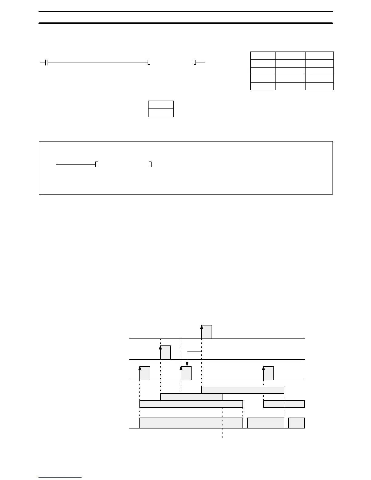
In the following example, CLI(154) is executed with S=00F2, so the recorded
interrupts for inputs 1, 4, 5, 6, and 7 are cleared. Recorded interrupts for inputs 0,
2, and 3 are unaffected.
Interrupt input 0
Interrupt input 1
Interrupt input 3
Memory status
Interrupt program execution
Interrupt program 3
CLI(154) used to clear interrupt 1
Interrupt program 0
Interrupt program 3
Ignored (interrupt already recorded)
0
1
3
Description
Interrupt Control Section 5-31

Table of Contents

Question and Answer IconNeed help?

Do you have a question about the Omron SYSMAC CV Series and is the answer not in the manual?

Omron SYSMAC CV Series Specifications

General IconGeneral
SeriesSYSMAC CV Series
TypePLC
Input Voltage100 to 240 VAC, 24 VDC
Number of InputsVaries by model
Number of OutputsVaries by model
I/O CapacityUp to 2048 points
I/O PointsVaries by model
Communication PortsRS-232C, RS-422/485
Programming LanguageLadder Logic
Power Supply100-240V AC or 24V DC
MountingDIN rail mounting
Operating Temperature0°C to 55°C

Summary

PRECAUTIONS

2 General Precautions

User must operate product per specifications; consult OMRON for non-manual conditions or critical systems.

3 Safety Precautions

Precautions regarding power supply, terminal touching, disassembly, repair, and battery handling.

4 Operating Environment Precautions

Guidelines for environmental conditions for PC system installation and operation.

5 Application Precautions

Precautions for safe PC system usage, grounding, power supply, wiring, and program changes.

SECTION 1 Introduction

SECTION 2 Hardware Considerations

2-3 Memory Cards

Covers file memory used to store programs and other data, including RAM, EPROM, and EEPROM types.

2-7 PC Configuration

Provides an overview of the PC configuration, including CPU Rack, Expansion CPU Rack, and Expansion I/O Rack.

SECTION 3 Memory Areas

3-2 Data Area Structure

Describes two sets of addresses for accessing PC memory: data area addresses and memory addresses.

3-3 CIO (Core I/O) Area

Details CIO Area addresses, divided into eight data areas for I/O control and internal data manipulation.

3-6 Auxiliary Area

Contains flags and control bits for monitoring and controlling PC operation, accessing clock pulses, and signaling errors.

SECTION 4 Writing Programs

4-1 Basic Procedure

Outlines basic steps for writing a program, including I/O device list and work bit allocation.

4-3 Basic Ladder Diagrams

Describes ladder diagrams, which consist of vertical lines (bus bars) and branching lines (instruction lines or rungs).

4-7 Controlling Bit Status

Lists instructions used to control individual bit status, such as OUTPUT, SET, RESET, and KEEP.

4-10 Programming Precautions

Provides guidelines on programming practices, such as unlimited conditions in series or parallel and avoiding vertical conditions.

SECTION 5 Instruction Set

5-6 Ladder Diagram Instructions

Covers instructions that correspond to ladder diagram conditions and logic block instructions for complex relationships.

5-7 Bit Control Instructions

Explains instructions used to control bit status by turning bits ON and OFF in different ways.

5-13 Timer and Counter Instructions

Details instructions for creating timers and counters, accessing PVs and Completion Flags.

5-15 Data Movement Instructions

Explains instructions used for moving data between different addresses in data areas.

5-16 Comparison Instructions

Covers instructions used for comparing data, affecting comparison flags and outputting results.

5-17 Conversion Instructions

Explains instructions that convert word data from one format to another, outputting converted data to specified result words.

SECTION 6 Program Execution Timing

6-2 Cycle Time

Explains operations affecting cycle time and I/O response time, and shows basic cycle time calculation.

6-5 I/O Response Time

Explains the time taken for the PC to output a control signal after receiving an input signal.

SECTION 7 PC Setup

SECTION 8 Error Processing

8-4 Error Messages

Classifies errors into initialization, non-fatal operating, and fatal operating errors for message display.

Appendices

A Instruction Set

Details all ladder diagram programming instructions, variations, and applicable data areas.

B Error and Arithmetic Flag Operation

Explains instructions affecting ER, CY, GR, LE, EQ, OF, UF, and N flags.

C PC Setup Default Settings

Lists default values for PC Setup parameters.

D Data Areas

Summarizes data areas in CV-series PCs, including CIO, Temporary Relay, and Auxiliary Areas.

Related product manuals