121
5-6 Ladder Diagram Instructions
Ladder Diagram Instructions include Ladder Instructions and Logic Block
Instructions. Ladder Instructions correspond to the conditions on the ladder
diagram. Logic Block Instructions are used to relate more complex parts of
the diagram that cannot be programmed with Ladder Instructions alone.
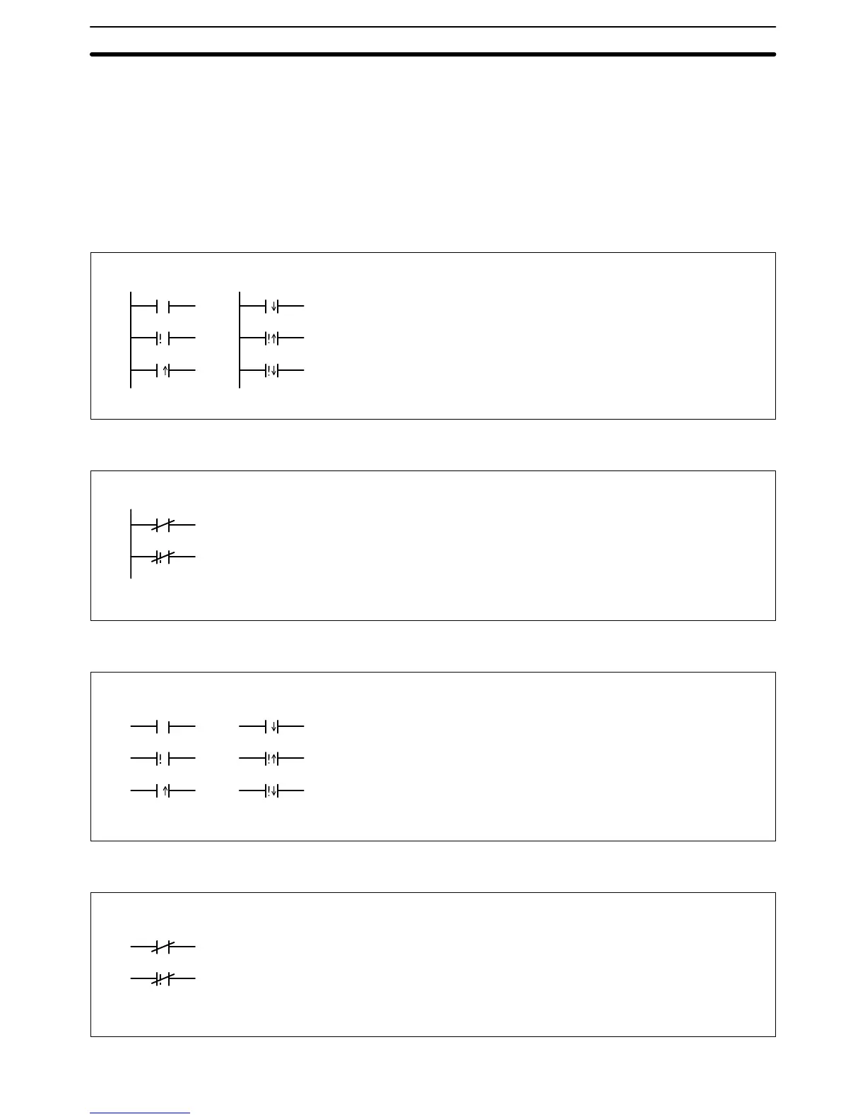
5-6-1 LOAD, LOAD NOT, AND, AND NOT, OR, and OR NOT
LOAD: LD
B: Bit CIO, G, A, T, C, ST, TN
Operand Data AreaLadder Symbols
Mnemonics
LD
j LD
! j LD
i LD
! i LD
! LD
B
B
B
B
B
B
LOAD NOT: LD NOT
B: Bit CIO, G, A, T, C, ST, TN
Operand Data AreaLadder Symbols
Mnemonics
LD NOT ! LD NOT
B
B
AND: AND
B: Bit CIO, G, A, T, C, ST, TN
Operand Data AreaLadder Symbols
Mnemonics
AND
j AND
! j AND
i AND
! i AND
! AND
B
B
B
B
B
B
AND NOT: AND NOT
B: Bit CIO, G, A, T, C, ST, TN
Operand Data AreaLadder Symbols
Mnemonics
AND NOT ! AND NOT
B
B
Ladder Diagram Instructions Section 5-6