122
OR: OR
B: Bit CIO, G, A, T, C, ST, TN
Operand Data AreaLadder Symbols
Mnemonics
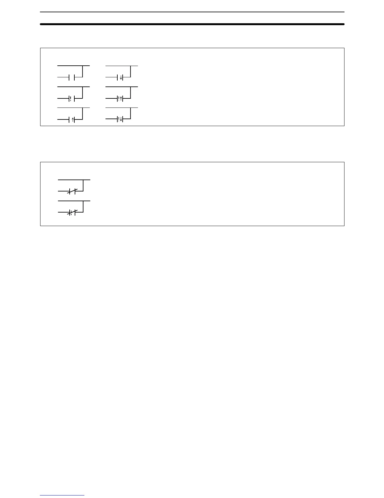
OR
j OR
! j OR
i OR
! i OR
! OR
B
B
B
B
B
B
OR NOT: OR NOT
B: Bit CIO, G, A, T, C, ST, TN
Operand Data AreaLadder Symbols
Mnemonics
OR NOT ! OR NOT
B
B
Description These six basic instructions correspond to the conditions on a ladder diagram.
As described in
Section 4 Writing Programs
, the status of the bits assigned to
each instruction determines the execution conditions for all other instructions.
Each of these instructions and each bit address can be used as many times as
required. Each bit can be used in as many of these instructions as required.
The status of the bit operand (B) assigned to LD or LD NOT determines the first
execution condition. AND takes the logical AND between the execution condi-
tion and the status of its bit operand; AND NOT, the logical AND between the
execution condition and the inverse of the status of its bit operand. OR takes the
logical OR between the execution condition and the status of its bit operand; OR
NOT, the logical OR between the execution condition and the inverse of the sta-
tus of its bit operand.
These six instructions use only one word of program memory, not two, when the
operand is in the CIO Area between CIO 000000 and CIO 051115, saving pro-
gram memory and reducing the instruction execution time. Two words of pro-
gram memory are required for all other operands.
TR bits are added to the program automatically when creating the program with
the ladder diagram using the CVSS. Input TR bits only when inputting the pro-
gram with mnemonics. The ladder symbol for loading TR bits is different from
that shown above for LD and LD NOT. Refer to
4-3-3 Ladder Instructions
for de-
tails.
Precautions There is no limit to the number of any of these instructions, or restrictions in the
order in which they must be used, as long as the program memory capacity of
the PC is not exceeded.
Flags There are no flags affected by these instructions.
Ladder Diagram Instructions Section 5-6