63
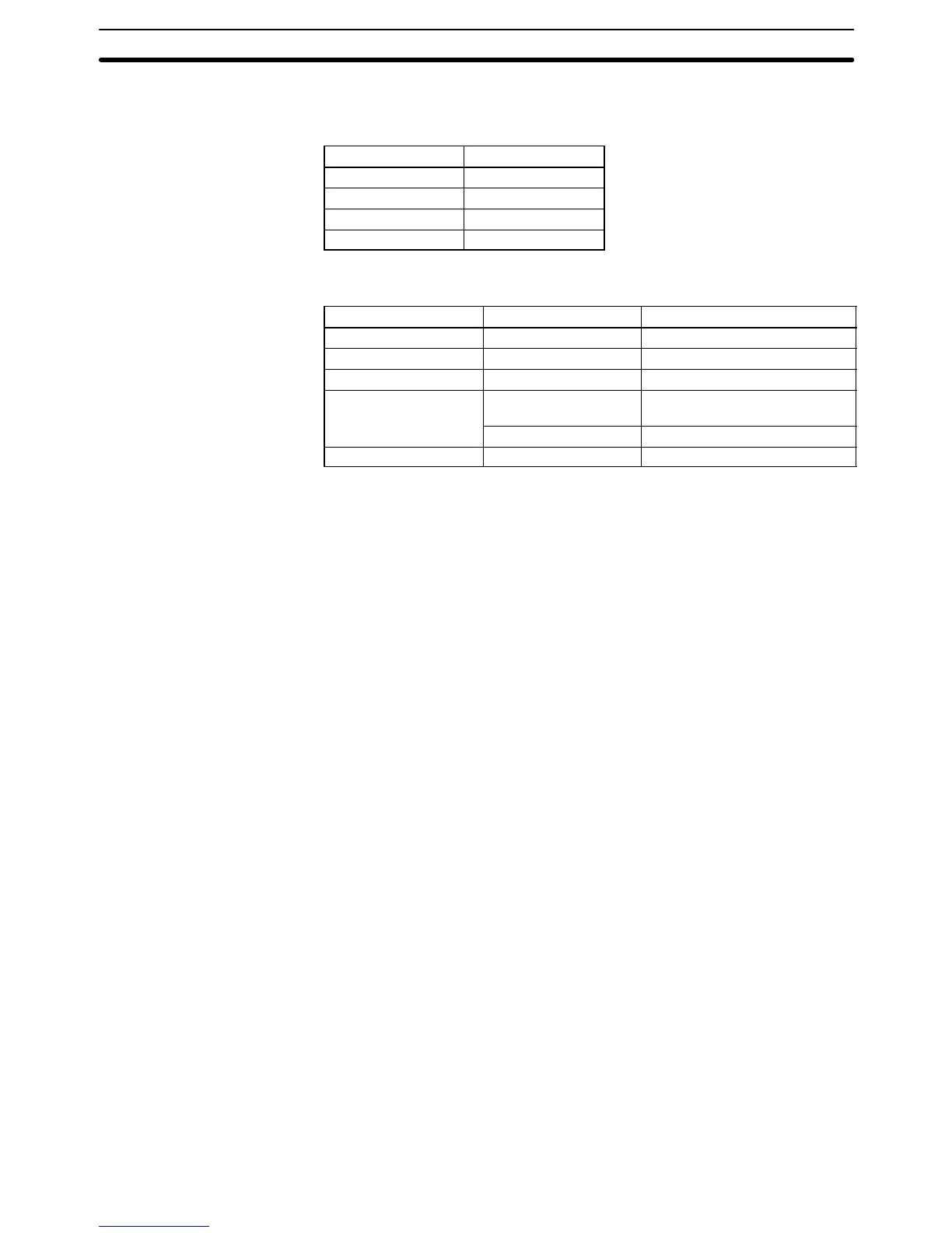
Information identifying the Slave Unit(s) involved is contained in words A480
through A499, which are divided into four groups of five words, one group for
each Master, as shown below.
Words Master number
A480 to A484 0
A485 to A489 1
A490 to A494 2
A495 to A499 3
Bits are turned ON to indicate which of the Slaves connected to the Master
was involved in the error, as shown below.
Word Bits Slave
First 00 to 15 Group-1 Slaves #0 to #15
Second 00 to 15 Group-1 Slaves #16 to #31
Third 00 to 15 Group-2 Slaves #0 to #15
Fourth 00 to 07 Slave Racks #0 to #7
(Group-3 Slaves)
08 to 15 Not used.
Fifth 00 to 15 Not used
3-6-37 CPU Bus Unit Error Flag and Unit Numbers
Bit A40207 is turned ON when a parity error occurs during the transmission of
data between the CPU and CPU Bus Units. The unit number of the CPU Bus Unit
involved is written to word A422.
Bits A42200 through A42215 correspond to CPU Bus Units #0 through #15, re-
spectively. When a CPU Bus Unit Error occurs, the bit corresponding to the unit
number of the CPU Bus Unit involved is turned ON.
3-6-38 I/O Verification Error Flag
Bit A40209 is turned ON when the Units mounted in the system disagree with
the I/O table registered in the CPU. To ensure proper operation, PC opera-
tion should be stopped, Units checked, and the I/O table corrected whenever
this flag goes ON.
3-6-39 SFC Non-fatal Error Flag and Error Code
Bit A40211 is turned ON if an error that does not stop operation occurs while the
SFC program is being executed. The error code is written to word A418. Refer to
Section 8 Error Processing
for details on the error codes.
3-6-40 Indirect DM BCD Error Flag
Bit A40212 is turned ON if the content of an indirectly addressed DM word is not
BCD when BCD is specified in the PC Setup.
The contents of indirectly addressed DM words can be set to either binary or
BCD with the PC Setup. Binary addresses will access memory according to PC
memory addresses. BCD will access other DM words according to DM Area ad-
dresses. If binary addresses are used, this flag will not operate.
3-6-41 Jump Error Flag
Bit A40213 is turned ON if there is no destination for a JMP(004) instruction.
3-6-42 FAL Flag and FAL Number
Bit A40215 is turned ON when the FAL(006) instruction is executed. The FAL
number is then written to words A430 to A461. Bits from A43001 to A46115 cor-
respond consecutively to FAL numbers 001 to 511
Auxiliary Area Section 3-6