!
50
Data Link Area The CPU Bus Link Area is disabled by default in the PC Setup and must be
enabled with the CVSS/SSS in order to use the Data Link Area.
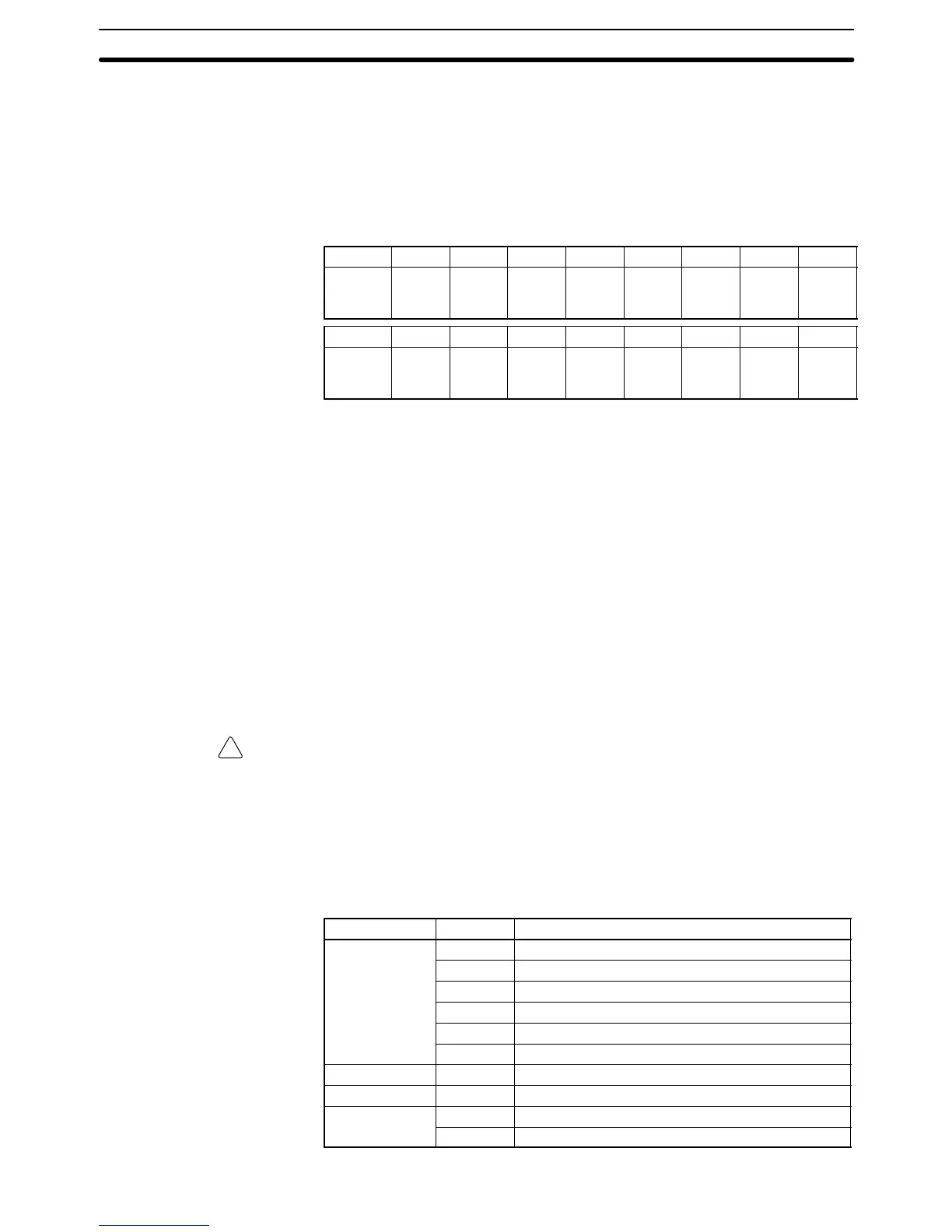
The 120 words of CPU Bus Link Area from G008 to G127 are used for outputs
from the CPU to BASIC Units. The 128 words from G128 to G255 are used for
outputs from the BASIC Units. These are divided into 16 groups of 8 words each
and allocated to CPU Bus Units according their unit number settings as shown in
the following tables. All words not output by a particular BASIC Unit are read by it
as inputs from the other BASIC Units.
Unit # 0 1 2 3 4 5 6 7
Words G128
to
G135
G136
to
G143
G144
to
G151
G152
to
G159
G160
to
G167
G168
to
G175
G176
to
G183
G184
to
G191
Unit # 8 9 10 11 12 13 14 15
Words G192
to
G199
G200
to
G207
G208
to
G215
G216
to
G223
G224
to
G231
G232
to
G239
G240
to
G247
G248
to
G255
When the PC Setup have been changed to enable the CPU Bus Link, bit 15 of
the first word allocated to each Unit (e.g., bit G12815 for Unit #0) will be OFF
during data reception.
3-6 Auxiliary Area
The Auxiliary Area contains flags and control bits used for monitoring and
controlling PC operation, accessing clock pulses, and signalling errors. Auxil-
iary Area word addresses range from A000 through A511; bit addresses,
from A00000 through A51115. Addresses A000 through A255 are read/write,
but addresses A256 through A511 are read only.
The Force Set/Reset operations from the CVSS/SSS behave like the
SET(016) and RSET(017) instructions when applied to words A000 through
A255.
Unused Auxiliary Area words and bits cannot be used as work words and
bits.
Caution The Auxiliary Area contains two sections. The section between A000 and A255
can be read from or written to from the user program. The section between A256
and A511, however, can be read from to access the data provided there, but it
cannot be written to from the user program.
The following table lists the functions of Auxiliary Area flags and control bits.
Most of these bits are described in more detail following the table. Descrip-
tions are in order by address, except that some bits/words with related func-
tions are explained together.
Word(s) Bit(s) Function
A000 00 to 10 Not used.
11 Restart Continuation Bit
12 IOM Hold Bit
13 Forced Status Hold Bit
14 Error Log Reset Bit
15 Output OFF Bit
A001 00 to 15 CPU Bus Unit Restart Bits
A002 to A004 00 to 15 Not used.
A005 00 to 07 SYSMAC BUS Error Check Bits
08 to 15 Not used.
Auxiliary Area Section 3-6