88
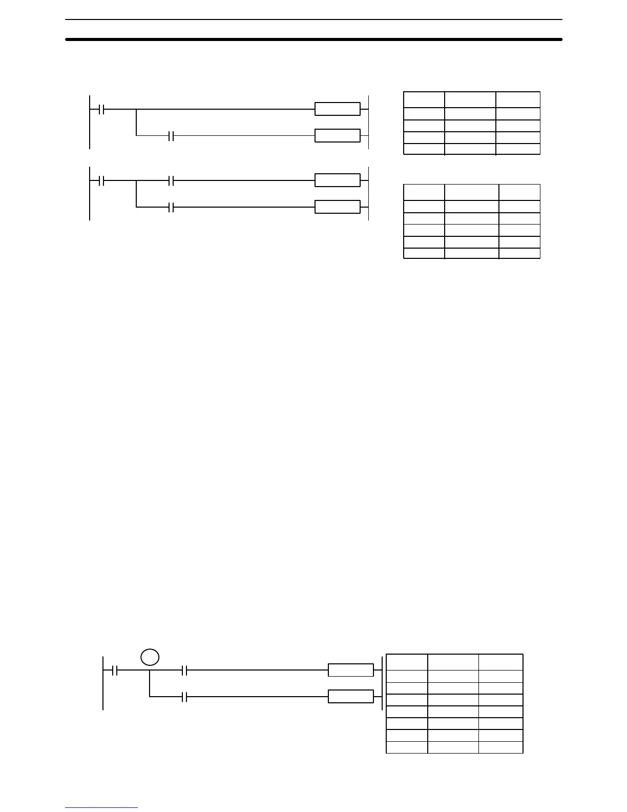
this. In both diagrams, instruction 1 is executed before returning to the branching
point and moving on to the branch line leading to instruction 2.
Instruction 2
00000 LD 000000
00001 AND 000001
00002 Instruction 1
00003 AND 000002
00004 Instruction 2
00000 LD 000000
00001 Instruction 1
00002 AND 000002
00003 Instruction 2
Branching
point
Diagram B: Incorrect Operation
Diagram A: Correct Operation
Address Instruction
Address Instruction
Operands
Operands
0000
00
0000
02
Instruction 1
0000
00
0000
02
Instruction 2
Instruction 1
Branching
point
0000
01
If, as shown in diagram A, the execution condition that existed at the branching
point cannot be changed before returning to the branch line (instructions at the
far right do not change the execution condition), then the branch line will be
executed correctly and no special programming measure is required.
If, as shown in diagram B, a condition exists between the branching point and the
last instruction on the top instruction line, the execution condition at the branch-
ing point and the execution condition after completing the top instruction line will
sometimes be different, making it impossible to ensure correct execution of the
branch line.
There are two means of programming branching programs to preserve the
execution condition. One is to use TR bits; the other, to use interlocks
(IL(002)/ILC(003)).
4-5-1 TR Bits
The TR area provides eight bits, TR0 through TR7, that can be used to tempo-
rarily preserve execution conditions. If a TR bit is placed at a branching point, the
current execution condition will be stored at the designated TR bit. When return-
ing to the branching point, the TR bit restores the execution status that was
saved when the branching point was first reached in program execution.
Note When programming in graphic ladder diagram form from the CVSS, it is not nec-
essary to input TR bits and none will appear on the screen. The CVSS will auto-
matically process TR bits for you as required and input them into the program.
You will have to input TR bit when programming in mnemonic form.
The previous diagram B can be written as shown below to ensure correct execu-
tion. In mnemonic code, the execution condition is stored at the branching point
using the TR bit as the operand of the OUTPUT instruction. This execution
condition is then restored after executing the right-hand instruction by using the
same TR bit as the operand of a LOAD instruction
Diagram B: Corrected Using a TR bit
TR0
Address Instruction
00000 LD 000000
00001 OUT TR0
00002 AND 000001
00003 Instruction 1
00004 LD TR0
00005 AND 000002
00006 Instruction 2
Operands
0000
00
0000
02
0000
01
Instruction 2
Instruction 1
Branching Instruction Lines Section 4-5