EasyManua.ls Logo

Omron SYSMAC CV Series User Manual

Omron SYSMAC CV Series
636 pages
To Next Page IconTo Next Page
To Previous Page IconTo Previous Page
Page #456 background imageLoading...
Page #456 background image
444
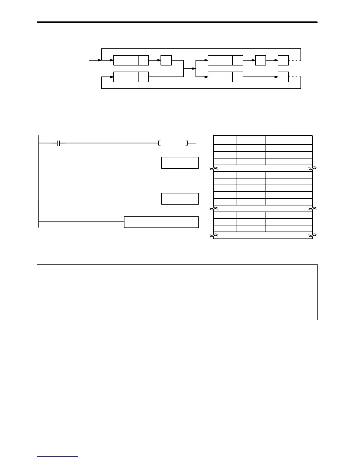
The execution flow for this example would be as shown below:
000000 ON A
000000 ON
000001 ON B
000001 OFF
C
C
Initial execution
The following example would work similarly, except that execution of
WAIT<005> would be based on an AND between the status of CIO 000001
and CIO 000002.
LD
AND
WAIT<005>
A
B
BEND<001>
C
000001
000002
Address Instruction Operands
000000 LD 000000
000001 BPRG(250) 01
A
000200 LD 000001
000201 AND 000002
000202 WAIT<005>
B
000300 BEND<001>
C
(250)
BPRG 01
0000
00
5-38-5 CONDITIONAL BLOCK EXIT: EXIT<006>
B: Bit CIO, G, A, T, C
Operand Data AreaLadder Symbol
EXIT<006>
EXIT<006> B
EXIT<006> NOT B
EXIT<006> and EXIT<006> NOT allow you to skip the portion of block pro-
gram from EXIT<006> to BEND<001> while B is ON or if a bit is not speci-
fied, while the execution condition is ON.
As long of the execution condition or operand bit of EXIT<006> is OFF, or the
operand bit of EXIT<006> NOT is ON, the block program will be executed as
normal. If the execution condition or operand bit of EXIT<006> is ON or the
operand bit of EXIT<006> NOT is OFF, only the part of the block program up
to the EXIT<006> or EXIT<006> NOT instruction will be executed and the
rest of the block program through BEND<001> will be skipped. If a bit is not
programmed for EXIT<006>, then the same operation will occur, but it will be
based on the status of the execution condition for EXIT<006>.
EXIT<006> NOT cannot be used without an operand bit.
Description
Precautions
(CVM1 V2)
Block Programming Instructions Section 5-38

Table of Contents

Question and Answer IconNeed help?

Do you have a question about the Omron SYSMAC CV Series and is the answer not in the manual?

Omron SYSMAC CV Series Specifications

General IconGeneral
SeriesSYSMAC CV Series
TypePLC
Input Voltage100 to 240 VAC, 24 VDC
Number of InputsVaries by model
Number of OutputsVaries by model
I/O CapacityUp to 2048 points
I/O PointsVaries by model
Communication PortsRS-232C, RS-422/485
Programming LanguageLadder Logic
Power Supply100-240V AC or 24V DC
MountingDIN rail mounting
Operating Temperature0°C to 55°C

Summary

PRECAUTIONS

2 General Precautions

User must operate product per specifications; consult OMRON for non-manual conditions or critical systems.

3 Safety Precautions

Precautions regarding power supply, terminal touching, disassembly, repair, and battery handling.

4 Operating Environment Precautions

Guidelines for environmental conditions for PC system installation and operation.

5 Application Precautions

Precautions for safe PC system usage, grounding, power supply, wiring, and program changes.

SECTION 1 Introduction

SECTION 2 Hardware Considerations

2-3 Memory Cards

Covers file memory used to store programs and other data, including RAM, EPROM, and EEPROM types.

2-7 PC Configuration

Provides an overview of the PC configuration, including CPU Rack, Expansion CPU Rack, and Expansion I/O Rack.

SECTION 3 Memory Areas

3-2 Data Area Structure

Describes two sets of addresses for accessing PC memory: data area addresses and memory addresses.

3-3 CIO (Core I/O) Area

Details CIO Area addresses, divided into eight data areas for I/O control and internal data manipulation.

3-6 Auxiliary Area

Contains flags and control bits for monitoring and controlling PC operation, accessing clock pulses, and signaling errors.

SECTION 4 Writing Programs

4-1 Basic Procedure

Outlines basic steps for writing a program, including I/O device list and work bit allocation.

4-3 Basic Ladder Diagrams

Describes ladder diagrams, which consist of vertical lines (bus bars) and branching lines (instruction lines or rungs).

4-7 Controlling Bit Status

Lists instructions used to control individual bit status, such as OUTPUT, SET, RESET, and KEEP.

4-10 Programming Precautions

Provides guidelines on programming practices, such as unlimited conditions in series or parallel and avoiding vertical conditions.

SECTION 5 Instruction Set

5-6 Ladder Diagram Instructions

Covers instructions that correspond to ladder diagram conditions and logic block instructions for complex relationships.

5-7 Bit Control Instructions

Explains instructions used to control bit status by turning bits ON and OFF in different ways.

5-13 Timer and Counter Instructions

Details instructions for creating timers and counters, accessing PVs and Completion Flags.

5-15 Data Movement Instructions

Explains instructions used for moving data between different addresses in data areas.

5-16 Comparison Instructions

Covers instructions used for comparing data, affecting comparison flags and outputting results.

5-17 Conversion Instructions

Explains instructions that convert word data from one format to another, outputting converted data to specified result words.

SECTION 6 Program Execution Timing

6-2 Cycle Time

Explains operations affecting cycle time and I/O response time, and shows basic cycle time calculation.

6-5 I/O Response Time

Explains the time taken for the PC to output a control signal after receiving an input signal.

SECTION 7 PC Setup

SECTION 8 Error Processing

8-4 Error Messages

Classifies errors into initialization, non-fatal operating, and fatal operating errors for message display.

Appendices

A Instruction Set

Details all ladder diagram programming instructions, variations, and applicable data areas.

B Error and Arithmetic Flag Operation

Explains instructions affecting ER, CY, GR, LE, EQ, OF, UF, and N flags.

C PC Setup Default Settings

Lists default values for PC Setup parameters.

D Data Areas

Summarizes data areas in CV-series PCs, including CIO, Temporary Relay, and Auxiliary Areas.

Related product manuals