37
The same timer and counter numbers can be used to designate either the
present value (PV) of the timer or counter, or the Completion Flag for the tim-
er or counter. This is explained in more detail in
3-9 Timer Area
and
3-10
Counter Area
.
Area Word designation Bit designation
CIO 0000 000015 (leftmost bit in word CIO 0000)
CIO 0252 025200 (rightmost bit in word CIO 0252)
DM D01250 Not possible
T T215 (designates PV) T215 (designates Completion Flag)
A A012 A01200
To designate a word by its PC Memory address, write the hexadecimal ad-
dress to an Index Register, DM, or EM word and indirectly address the oper-
and through that register or word. Refer to
3-11 DM and EM Areas
and
3-12
IR and DR Areas
for details on indirect addressing.
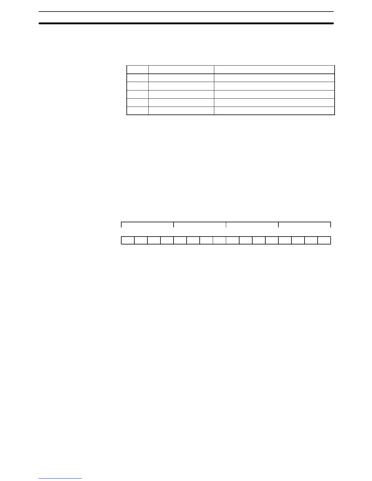
Word data input as decimal values is stored in binary-coded decimal (BCD);
word data entered as hexadecimal is stored in binary form. Each four bits of
a word represent one digit, either a hexadecimal or decimal digit, numerically
equivalent to the value of the binary bits. One word of data thus contains four
digits, which are numbered from right to left. These digit numbers and the
corresponding bit numbers for one word are shown below.
Bit number
Contents 0000000000000000
15 14 13 12 11 10 09 08 07 06 05 04 03 02 01 00
Digit number 3210
When referring to the entire word, the digit numbered 0 is called the right-
most digit; the one numbered 3, the leftmost digit.
When inputting data, it must be input in the proper form for the intended pur-
pose. This is no problem when designating bits, which are turned ON (equiv-
alent to a binary value of 1) or OFF (a binary value of 0). When inputting
word data, however, it is important to input it either as decimal or as hexade-
cimal, depending on what is called for by the instruction it is to be used for.
Section 5 Instruction Set
specifies when a particular form of data is required
for an instruction.
Binary and hexadecimal can be easily converted back and forth because
each four bits of a binary number is numerically equivalent to one digit of a
hexadecimal number. The binary number 0101111101011111 is converted to
hexadecimal by considering each set of four bits in order from the right.
Binary 1111 is hexadecimal F; binary 0101 is hexadecimal 5. The hexadeci-
mal equivalent would thus be 5F5F, or 24,415 in decimal (16
3
x 5 + 16
2
x 15
+ 16 x 5 + 15).
Decimal and BCD are easily converted back and forth. In this case, each
BCD digit (i.e., each group of four BCD bits) is numerically equivalent to the
corresponding decimal digit. The BCD bits 0101011101010111 are converted
to decimal by considering each four bits from the right. Binary 0101 is deci-
mal 5; binary 0111 is decimal 7. The decimal equivalent would thus be 5,757.
Note that this is not the same numeric value as the hexadecimal equivalent
of 0101011101010111, which would be 5,757 hexadecimal, or 22,359 in deci-
mal (16
3
x 5 + 16
2
x 7 + 16 x 5 + 7).
Data Structure
Converting Different Forms
of Data
Data Area Structure Section 3-2