143
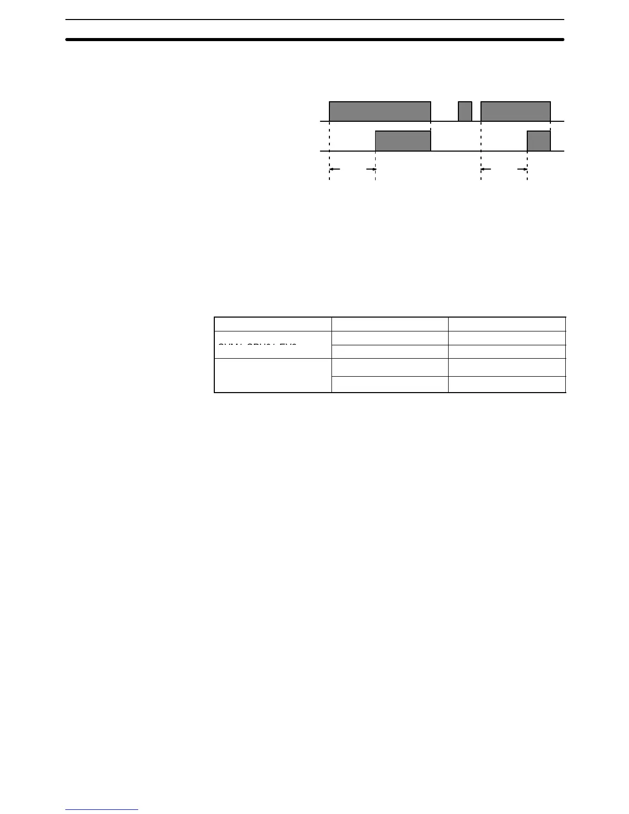
The following figure illustrates the relationship between the execution condition
for TIM and the Completion Flag assigned to it.
Execution condition
Completion Flag
ON
OFF
ON
OFF
SV SV
Precautions SV must be between 000.0 and 999.9 and must be BCD. The decimal point is not
entered.
Each timer number can be used to define only one timer instruction unless the
timers are never active simultaneously.
Timer numbers are as shown in the following table. The “high-speed” timer num-
bers should not be used for other timer instructions if they are required for
TIMH(015). Refer to
5-13-2 HIGH-SPEED TIMER: TIMH(015)
for details.
PC Instructions Timer numbers
CV500 or
,
CVM1-CPU21-EV2
High-speed timers T0000 through T0255
When using SFC, TIM and TIMH(015) timers are reset at the transition between
steps. If required, use the hold option with the action qualifier to prevent timers
from being automatically resetting at transitions.
Timers in interlocked program sections are reset when the execution condition
for IL(002) is OFF. Timers in jumped program sections continue timing. Power
interruptions also reset timers. If a timer that is not reset under these conditions
is desired, Auxiliary Area clock pulse bits can be counted to produce timers us-
ing CNT. Refer to
5-13-6 COUNTER: CNT
for details.
If the same timer number is used in different SFC program steps, or the IOM
Hold Bit and PC Setup are set to retain IOM (which includes timer PVs and
Completion Flags), the timer must be reset before starting it to prevent possible
malfunctions.
A delay of one cycle is sometimes required for a Completion Flag to be turned
ON after the timer times out.
If you convert a TIM instruction to a TIMH(015) instruction using online program-
ming operations, always reset the TIM instruction’s Completion Flag. Proper op-
eration will not be possible unless the Completion Flag is reset.
Note: Refer to page 115 for general precautions on operand data areas.
Flags ER (A50003): Content of *DM word is not BCD when set for BCD.
Content of S (SV) is not BCD.
Examples All of the following examples use OUT in diagrams that would generally be used
to control output bits in the I/O Area. These diagrams can be modified to control
execution of other instructions.
Timer and Counter Instructions Section 5-13