171
After the bits have been shifted, the status of the bits from which data was shifted
(i.e., the number of bits shifted, beginning with the rightmost bit of the specified
word) will be set to “0” or to the status of the LSB, depending on the control word
setting.
Number of bits shift (00 to 32)
Control Word Contents
MSB LSB
Status of remaining bits
0: 0
8: Status of LSB
0
Precautions Refer to page 115 for general precautions on operand data areas.
Flags ER (A50003): Number of bits to shift is out of range.
Content of a*DM word is not BCD when set for BCD.
CY (A50004): “1” has been shifted to CY.
EQ (A50006) Content of words D and D+1 after the shift is all zeros.
N (A50008) Same status as leftmost bit (MSB) of word D+1 after shift.
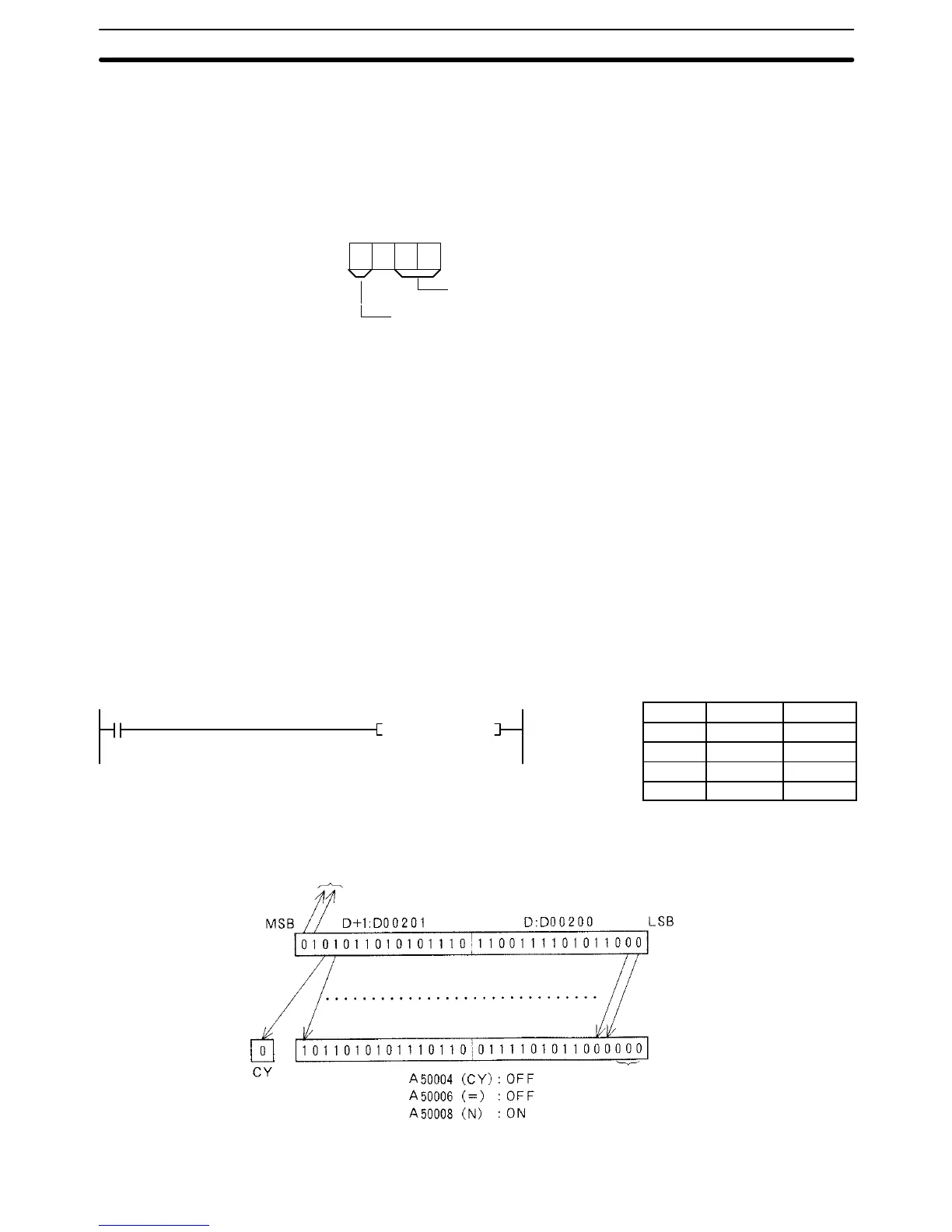
Example When CIO 000000 is ON in the following example, the 32 bits in D00201 and
D00200 are shifted three bits to the left. The status of the three rightmost bits of
D00200 are set to “0.”
Address Instruction Operands
00000 LD 000000
00001 NSLL(058)
D00200
#8003
0 entered.
Lost
Shift Instructions Section 5-14
(058)
NSLL D00200 #8003
0000
00