372
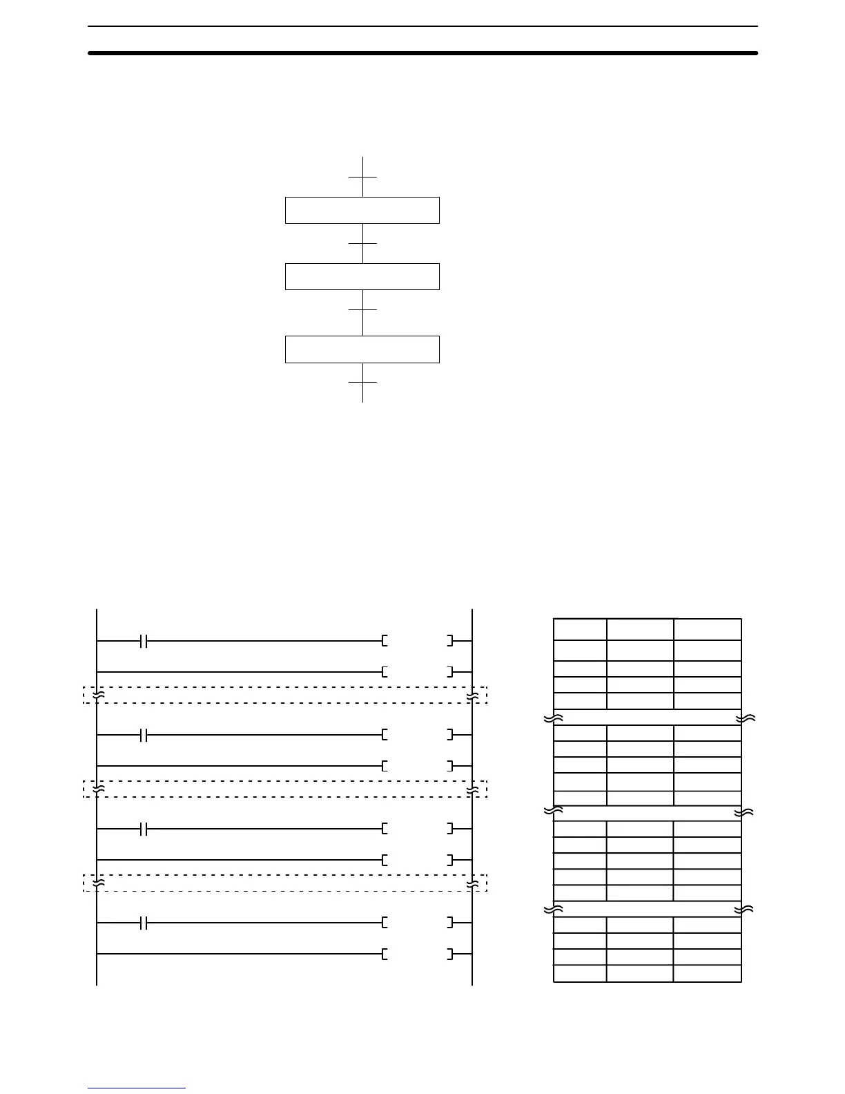
The following diagram demonstrates the flow of processing and the switches
that are used for execution control.
Process A
Process B
Process C
Loading
Part Installation
Inspection/discharge
SW1
SW2
SW3
SW4
The program for this process, shown below, utilizes the most basic type of step
programming: each step is completed by a unique SNXT(009) that starts the
next step. Each step starts when the switch that indicates the previous step has
been completed turns ON.
(009)
SNXT 012800
(008)
STEP 012800
(009)
SNXT 012801
(008)
STEP 012801
(009)
SNXT 012802
(008)
STEP 012802
(009)
SNXT 012803
(008)
STEP 012803
0000
01
0000
02
0000
03
0000
04
Programming for process A
Programming for process B
Programming for process C
Process
A started.
Process
A reset.
Process
B started.
Process
B reset.
Process
C started.
Process
C reset.
00000 LD 000001
00001 SNXT(009) 012800
00002 STEP(008) 012800
Process A
00100 LD 000002
00101 SNXT(009) 012801
00102 STEP(008) 012801
Process B
00100 LD 000003
00101 SNXT(009) 012802
00102 STEP(008) 012802
Process C
00200 LD 000004
00201 SNXT(009) 012803
00202 STEP(008) 012803
Address Instruction Operands
SW1
SW2
SW3
SW4
STEP DEFINE and STEP START: STEP(008)/SNXT(009) Section 5-29