375
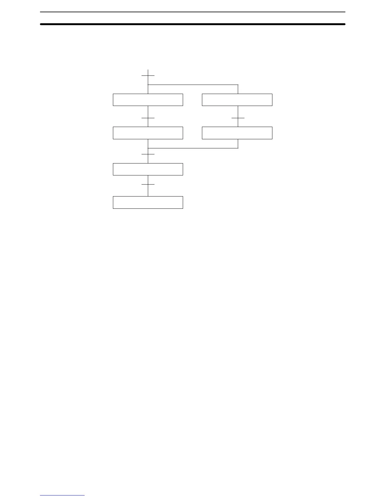
The following diagram demonstrates the flow of processing and the switches
that are used for execution control. Here, process A and process C are started
together. When process A finishes, process B starts; when process C finishes,
process D starts. When both processes B and D have finished, process E starts.
Process A
Process E
End
Process C
SW7
Process B Process D
SW3
SW4
SW 1 and SW2 both ON
SW5 and SW6 both ON
The program for this operation, shown below, starts with two SNXT(009) instruc-
tions that start processes A and C. These instructions branch from the same in-
struction line and are always executed together, starting steps for both A and C.
When the steps for both A and C have finished, the steps for process B and D
begin immediately.
STEP DEFINE and STEP START: STEP(008)/SNXT(009) Section 5-29