EasyManua.ls Logo

Omron SYSMAC CV Series User Manual

Omron SYSMAC CV Series
636 pages
To Next Page IconTo Next Page
To Previous Page IconTo Previous Page
Page #409 background imageLoading...
Page #409 background image
(180)
FILR 0300 D01000 0500
0000
00
397
When FILR(180) is executed, the CPU first checks whether the ER Flag
(A50003) is ON, then processes the data transfer and following instructions in
parallel, so check the Memory Card Instruction Flag (A34313) to verify that
FILR(180) has been completed correctly.
The number of words to transfer (N) must be BCD.
If bit 04 of C is ON, C+5 must be BCD.
If N exceeds the number of words remaining in the file, only the words in the file
will be transferred and no error will occur.
Write the execution condition for FLSP(183) so that the instruction will not be
executed if the Memory Card Instruction Flag (A34313) is ON (when another
memory card instruction is being executed).
Note Refer to page 115 for general precautions on operand data areas.
Flags ER (A50003): N is not BCD.
Bit 04 of C is ON, but the content C+5 is not BCD.
Content of *DM word is not BCD when set for BCD.
A Memory Card is not mounted.
A34310: The file not read if the offset in C+5 is larger than the file.
A34311: The specified file doesn’t exist on the card.
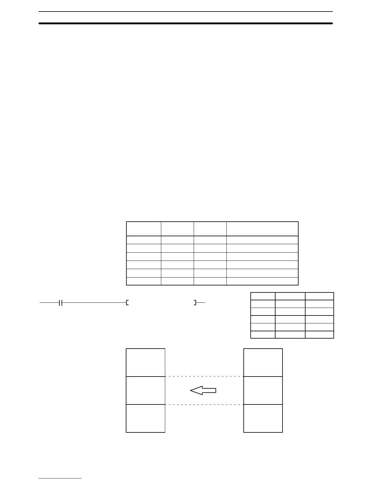
In the following example, 20 words, beginning from the 17
th
word of the file, are
transferred from memory card data file “ABCD” to D01000 to D01019.
Here, the content of CIO 0300 would be 0020 (BCD) to indicate reading 20
words. The contents of the control words would be as follows:
Word Leftmost
byte
Rightmost
byte
Meaning
CIO 0500 0 0 1 0 Enable offset
CIO 0501 4 1 4 2 A B
CIO 0502 4 3 4 4 C D
CIO 0503 2 0 2 0 Indicates end of name
CIO 0504 2 0 2 0 Indicates end of name
CIO 0505 0 0 1 7 Offset
Address Instruction Operands
00000 LD 000000
00001 FILR(180)
0300
D01000
0500
Memory Card
ABCD.IOM
D01000
D01019
PC Memory
17th word
36th word
Precautions
Example
Memory Card Instructions Section 5-34

Table of Contents

Question and Answer IconNeed help?

Do you have a question about the Omron SYSMAC CV Series and is the answer not in the manual?

Omron SYSMAC CV Series Specifications

General IconGeneral
SeriesSYSMAC CV Series
TypePLC
Input Voltage100 to 240 VAC, 24 VDC
Number of InputsVaries by model
Number of OutputsVaries by model
I/O CapacityUp to 2048 points
I/O PointsVaries by model
Communication PortsRS-232C, RS-422/485
Programming LanguageLadder Logic
Power Supply100-240V AC or 24V DC
MountingDIN rail mounting
Operating Temperature0°C to 55°C

Summary

PRECAUTIONS

2 General Precautions

User must operate product per specifications; consult OMRON for non-manual conditions or critical systems.

3 Safety Precautions

Precautions regarding power supply, terminal touching, disassembly, repair, and battery handling.

4 Operating Environment Precautions

Guidelines for environmental conditions for PC system installation and operation.

5 Application Precautions

Precautions for safe PC system usage, grounding, power supply, wiring, and program changes.

SECTION 1 Introduction

SECTION 2 Hardware Considerations

2-3 Memory Cards

Covers file memory used to store programs and other data, including RAM, EPROM, and EEPROM types.

2-7 PC Configuration

Provides an overview of the PC configuration, including CPU Rack, Expansion CPU Rack, and Expansion I/O Rack.

SECTION 3 Memory Areas

3-2 Data Area Structure

Describes two sets of addresses for accessing PC memory: data area addresses and memory addresses.

3-3 CIO (Core I/O) Area

Details CIO Area addresses, divided into eight data areas for I/O control and internal data manipulation.

3-6 Auxiliary Area

Contains flags and control bits for monitoring and controlling PC operation, accessing clock pulses, and signaling errors.

SECTION 4 Writing Programs

4-1 Basic Procedure

Outlines basic steps for writing a program, including I/O device list and work bit allocation.

4-3 Basic Ladder Diagrams

Describes ladder diagrams, which consist of vertical lines (bus bars) and branching lines (instruction lines or rungs).

4-7 Controlling Bit Status

Lists instructions used to control individual bit status, such as OUTPUT, SET, RESET, and KEEP.

4-10 Programming Precautions

Provides guidelines on programming practices, such as unlimited conditions in series or parallel and avoiding vertical conditions.

SECTION 5 Instruction Set

5-6 Ladder Diagram Instructions

Covers instructions that correspond to ladder diagram conditions and logic block instructions for complex relationships.

5-7 Bit Control Instructions

Explains instructions used to control bit status by turning bits ON and OFF in different ways.

5-13 Timer and Counter Instructions

Details instructions for creating timers and counters, accessing PVs and Completion Flags.

5-15 Data Movement Instructions

Explains instructions used for moving data between different addresses in data areas.

5-16 Comparison Instructions

Covers instructions used for comparing data, affecting comparison flags and outputting results.

5-17 Conversion Instructions

Explains instructions that convert word data from one format to another, outputting converted data to specified result words.

SECTION 6 Program Execution Timing

6-2 Cycle Time

Explains operations affecting cycle time and I/O response time, and shows basic cycle time calculation.

6-5 I/O Response Time

Explains the time taken for the PC to output a control signal after receiving an input signal.

SECTION 7 PC Setup

SECTION 8 Error Processing

8-4 Error Messages

Classifies errors into initialization, non-fatal operating, and fatal operating errors for message display.

Appendices

A Instruction Set

Details all ladder diagram programming instructions, variations, and applicable data areas.

B Error and Arithmetic Flag Operation

Explains instructions affecting ER, CY, GR, LE, EQ, OF, UF, and N flags.

C PC Setup Default Settings

Lists default values for PC Setup parameters.

D Data Areas

Summarizes data areas in CV-series PCs, including CIO, Temporary Relay, and Auxiliary Areas.

Related product manuals