Appendix AInstruction Set
523
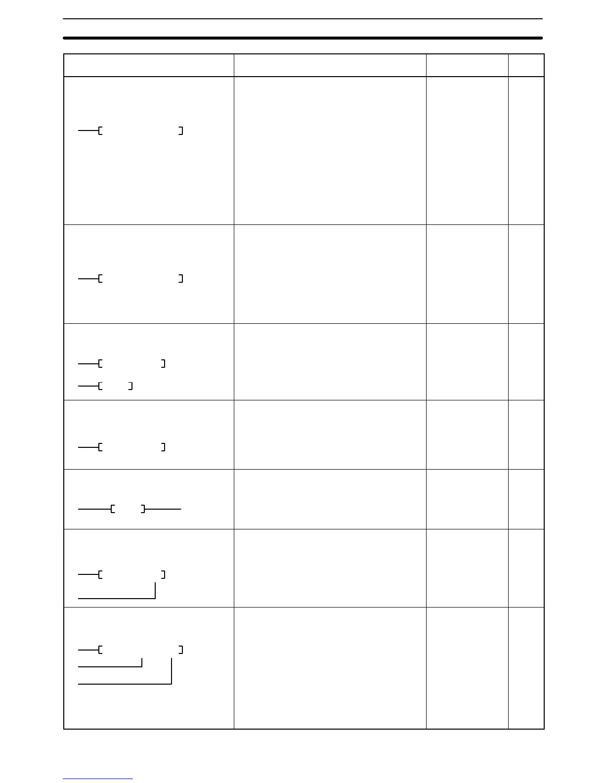
Name, mnemonic, variations,
and symbol
PageOperand data
areas
Function
FAILURE ALARM
FAL, jFAL
(006)
FAL N M
Outputs a FAL error number (N) and
generates a non-fatal error when the
execution condition is ON. N must be between
001 and 511. When the FAL number is
generated, a corresponding bit is turned ON in
the FAL output area, and the FAL number is
output to A400. A 16 character message
stored in M to M+7 can be output to a
Peripheral Device if desired. The same FAL
numbers are used for both FAL(006) and
FALS(007), except 000. N can be set to 000 to
reset a single FAL error designated by M or to
reset all non-fatal errors by designating FFFF
for M.
N:
#
M:
CIO
G
A
#
DM
354
FAILURE ALARM
FALS, jFALS
(007)
FALS N M
Outputs the FAL error number (N) and
generates a fatal error when the execution
condition is ON. N must be between 001 and
511. The error number is output to A400. The
same FAL numbers are used for both
FAL(006) and FALS(007), except N cannot be
defined as 000 with FALS(007). A 16
character message stored in M to M+7 can be
output to a Peripheral Device if desired.
N:
#
M:
CIO
G
A
#
DM
354
STEP DEFINE
STEP
(008)
STEP B
(008)
STEP
When used with a control bit (B), defines the
start of a new step and resets the previous
step. When used without B, it defines the end
of step execution. The steps referred to here
are for step execution of ladder diagram
programs and are not related to SFC.
B:
CIO
G
A
368
STEP START
SNXT
(009)
SNXT B
Used with a control bit (B) to indicate the end
of the previous step, reset the previous step,
and start the step which has been defined with
the same control bit. The steps referred to
here are for step execution of ladder diagram
programs and are not related to SFC.
B:
CIO
G
A
368
NOT
NOT
(010)
NOT
NOT(010) is used along an instruction line to
invert the current execution condition. It
cannot be placed at the end of an instruction
line, only between conditions or between a
condition and a right-hand instruction.
None 125
KEEP
KEEP, !KEEP
(011)
KEEP B
S
R
Defines a bit (B) as a latch controlled by the
set (S) and reset (R) inputs. B will turn ON
when S turns ON and will turn OFF when R
turns OFF. B will turn OFF if both S and R are
ON.
B:
CIO
G
A
132
REVERSIBLE COUNTER
CNTR
(012)
CNTR N S
II
DI
R
Increases or decreases the PV by one
whenever the increment input (II) or
decrement input (DI) condition, respectively,
go from OFF to ON. S (set value): 0 to 9999;
R: reset input. Each counter number can be
used in only one counter instruction (CNT,
CNTR(012), and TCNT(123)), unless the
counters are never active simultaneously. The
counter number can be entered as a constant
or indirectly addressed by placing the address
of the present value of the counter in an Index
Register.
N:
#
S:
CIO
G
A
T/C
#
DM
DR
IR
156